Operation
Switching ON/OFF
Before switching on the inverter, ensure that all wiring is complete and the battery connection is secure.
- To turn on the inverter, press the ON/OFF button.
- When the inverter is powered by PV or grid supply but has no battery connected, the LCD screen will still illuminate, even if the ON/OFF button is off. The display will indicate that the system is in standby mode.
- In this state, press the ON/OFF button, then select ‘No Battery’ from the startup options. The system will begin operating using available PV or grid power only.
The inverter can operate without a battery if either PV or grid input is present. However, battery features such as backup and storage will not be available in this mode.
Display
The LCD display screen is situated on the front of the Three-Phase LP IP65, this is where you can control and operate
the system.
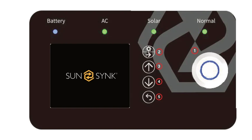
- Power - to turn the system on / off.
- Settings / Select - to operate the settings menu & to select.
- Up - to navigate up.
- Down - to navigate down.
- Home / Back - to go back to the home menu & to navigate backwards.

LED Indicators
| TYPE | INDICATION | DESCRIPTION |
|---|---|---|
| BATTERY | GREEN | CHARGING |
| BLUE | DISCHARGING | |
| AC | GREEN | AC CONNECTED |
| OFF | AC OFF | |
| SOLAR | GREEN | SOLAR ON |
| OFF | SOLAR OFF | |
| NORMAL | GREEN | INVERTER RUNNING |
| RED | SYSTEM FAULT | |
| OFF | INVERTER NOT RUNNING |
LCD Operation Flow Chart
Solar
Solar Graph
AC Load
Status Page
System Flow Chart
Grid
Grid Graph

Battery Load
Battery Info
Home
Battery %
BMS
Home
Basic Setup
Quick Control
Battery Setup
Settings
BMS
System Flow Chart
Grid Setup
System Information
System Mode
Advance
Fault Code
Home
The Home Screen serves as the central dashboard of the Three-Phase LP IP65 Inverter, providing users with an immediate and intuitive overview of the system's key metrics. From here, users can monitor the most important data, navigate to different sections, and control essential functions with ease.
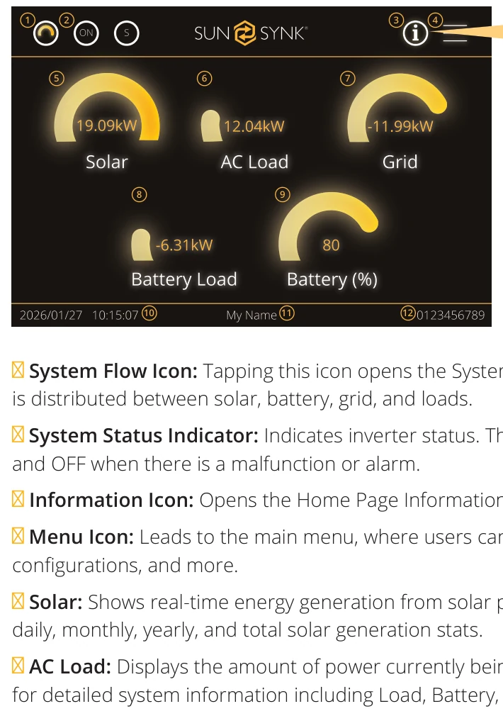
① System Flow Icon: Tapping this icon opens the System Flow Chart screen, providing a visual map of how power is distributed between solar, battery, grid, and loads.
② System Status Indicator: Indicates inverter status. The icon shows ON when the inverter is operating normally and OFF when there is a malfunction or alarm.
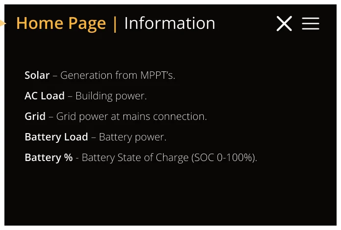
③ Information Icon: Opens the Home Page Information screen, which explains each data icon.
④ Menu Icon: Leads to the main menu, where users can access setup options, smart features, advanced configurations, and more.
⑤ Solar: Shows real-time energy generation from solar panels. Tap to access the Solar Setup screen, which includes daily, monthly, yearly, and total solar generation stats.
⑥ AC Load: Displays the amount of power currently being used by the AC loads. Tap to access the AC Load screen for detailed system information including Load, Battery, Grid and Solar.
⑦ Grid: Indicates the power being drawn from or exported to the grid. Tap to access the Grid screen and view energy import/export graphs over time.
⑧ Battery Load: Displays the real-time battery power flow. This value shows whether the battery is charging or discharging, in kilowatts. Tapping this icon opens the Battery Information screen where users can see the battery voltage, current, charging/discharging status and state of charge (SOC).
⑨ Battery %: Indicates the State of Charge (SOC) of the battery, displayed as a percentage (0–100%). Tapping this icon opens the Li BMS (Battery Management System) screen, where users can monitor battery performance in greater detail.
⑩ Date & Time: Displays the current system date and time in real time (e.g., 01/02/2024 – 13:15:21).
⑪ Username: Indicates the name of the current user or administrator operating the interface (e.g., “My Name”).
⑫ System ID: Displays the inverter’s unique system identifier (e.g., 0000000000), useful for system tracking, service, and diagnostics.
Home | Solar
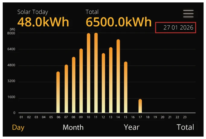
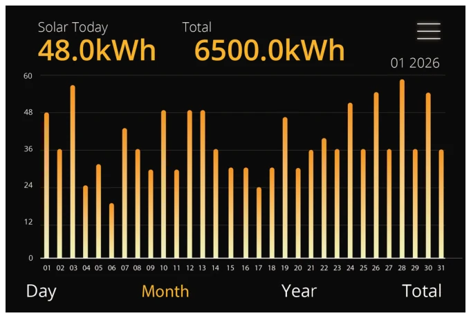
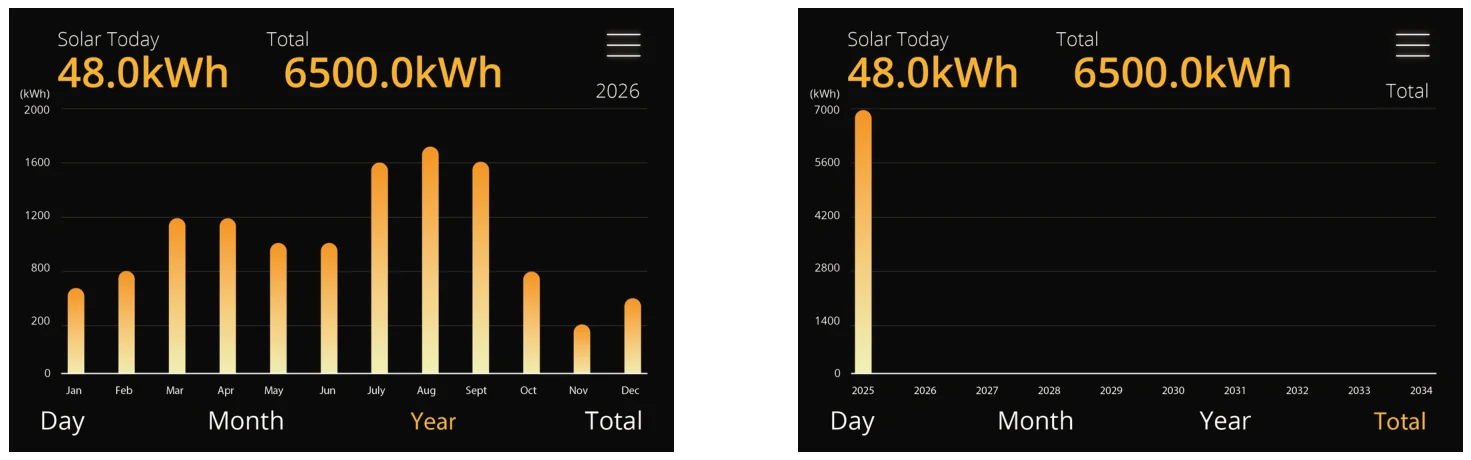
The Solar screen displays the total solar energy produced over various time periods. It provides a clear graphical breakdown of solar generation statistics by day, month, year, and overall system lifetime. On the daily chart, you can click on the date to check the Solar PV (photovoltaic) output for the current week.
Access this screen by tapping the “Solar” icon on the Home screen.
Home | AC Load
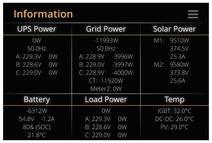
The AC Load screen provides a real-time overview of power flow across all major system components, including the battery, grid, solar PV input, inverter output, connected loads, and temperature. This page is designed to give users a full picture of energy usage and system performance.
To access this page, tap the "AC Load" dial on the Home Screen.
COLUMN DESCRIPTIONS
- UPS Column: Displays UPS output power and voltage delivered to the system.
- Grid Column: Shows power exchange with the grid.
- Positive = importing power, Negative = exporting power.
- Displays frequency, voltage, CT coil value, and meter 2 power.
- Solar Column (MPPT 1 & 2): Shows solar generation statistics for each Maximum Power Point Tracker.
- Includes power, voltage, and current per MPPT input.
- Battery Column: Displays total power from the battery, including SOC, voltage, current, and temperature.
- A negative value indicates discharge.
- A positive value indicates charging.
- Temperature reads 0°C if the sensor is disconnected.
- Displays internal temperatures from DC transformer and AC heatsink.
- Performance begins degrading at 110°C and shuts down automatically for safety.
- Load Column: Shows the total load power (W) drawn from the inverter.
- Temp Column: Shows the temperatures of the IGBT, DC-DC converter, and PV components.
- The system will trigger an error protection and halt operation if the temperature reaches the following values:
- 83°C for IGBT
- 105°C for DC-DC Converter
- 78°C for PV
Home | Grid
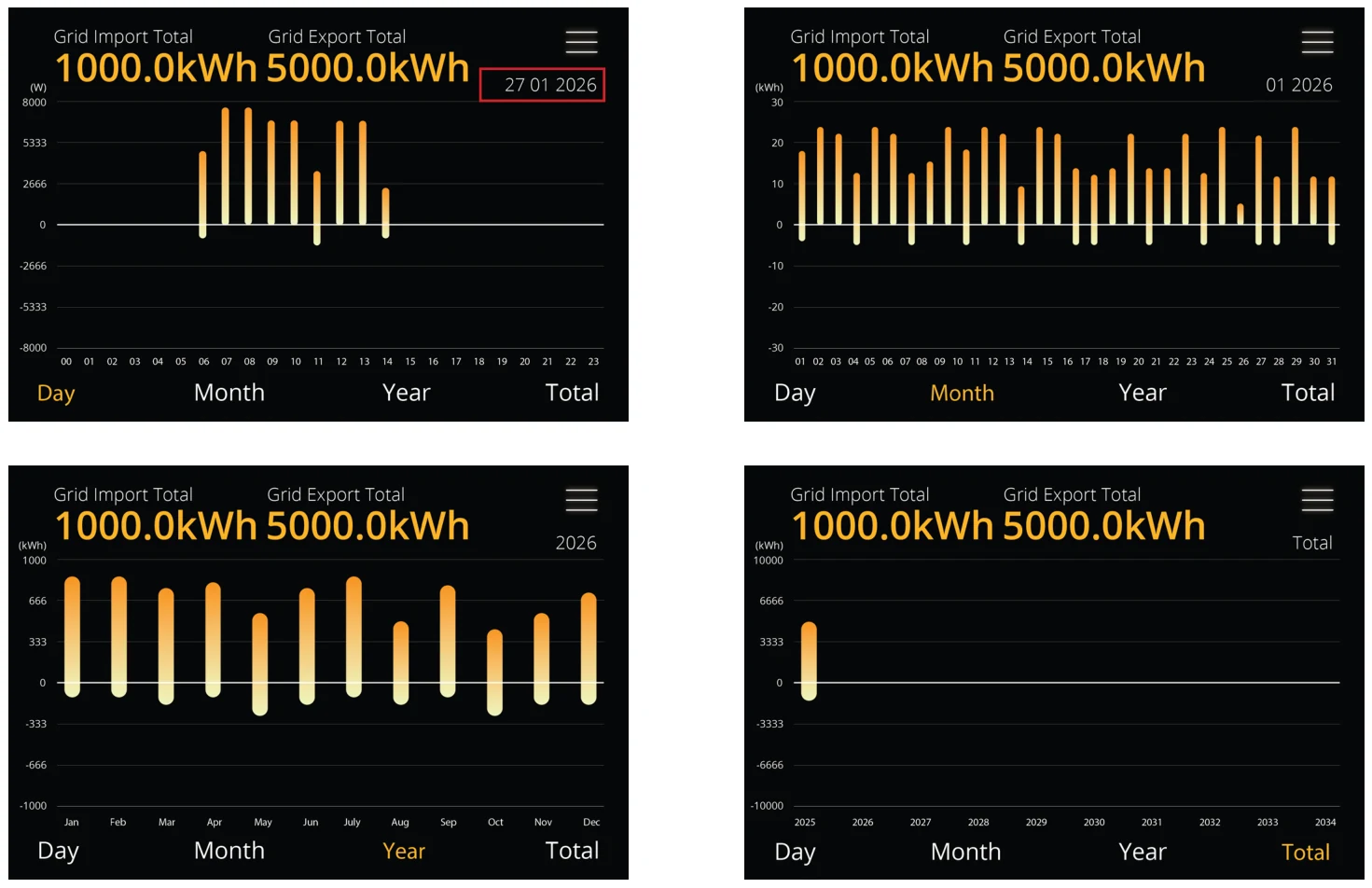
The Grid screen provides a graphical overview of energy imported from and exported to the grid. Users can monitor grid activity over different time periods - daily, monthly, yearly, and total system lifetime - to better understand consumption patterns and export performance. On the daily chart, you can click on the date to query the electricity purchase and sales volume of the power grid in the past seven days.
Access this screen by tapping the “Grid” icon on the Home screen.
Home | Battery Load
This page provides real-time insights into battery performance. It displays key parameters such as battery voltage, current, charge status, and the state of charge (SOC).
You can access this screen by tapping the Battery Load icon on the Home screen.

Home | Battery %
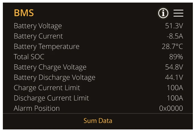
This page displays detailed information from the Battery Management System (BMS), providing a real-time overview of the battery’s status and performance metrics.
To access this page, tap the “Battery %” icon on the Home screen. All data presented is sourced directly from the connected battery’s BMS. An additional screen “Alarm Position Information” is accessed by pressing “Alarm Position” on the BMS page. The alarm codes and descriptions found on the “Alarm Position Information” screen only apply to Pylontech batteries.
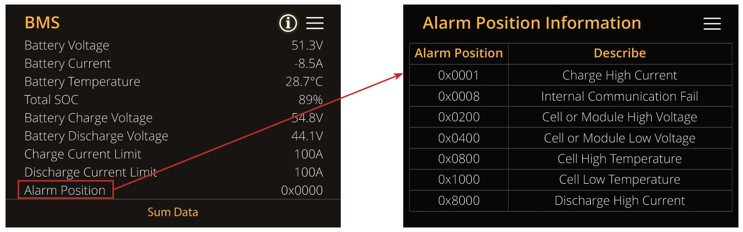
The BMS panel provides a high-level summary of key operational values:
- Battery Voltage: Current voltage across the battery pack (e.g., 52.0V)
- Battery Current: Positive = charging, Negative = discharging (e.g., 30A = charge)
- Battery Temperature: Internal temperature in °C (e.g., 33.0°C)
- Total SOC: State of Charge – current battery level (e.g., 80%)
- Battery Charge Voltage: Target voltage for charging (e.g., 40.0V)
- Battery Discharge Voltage: Target voltage for discharging (e.g., 52.0V)
- Charge Current Limit: Max current allowed when charging (e.g., 40A)
- Discharge Current Limit: Max current allowed when discharging (e.g., 50A)
- Alarm Position: BMS alarm code status (e.g., 0x0000 = no active faults).
Menu
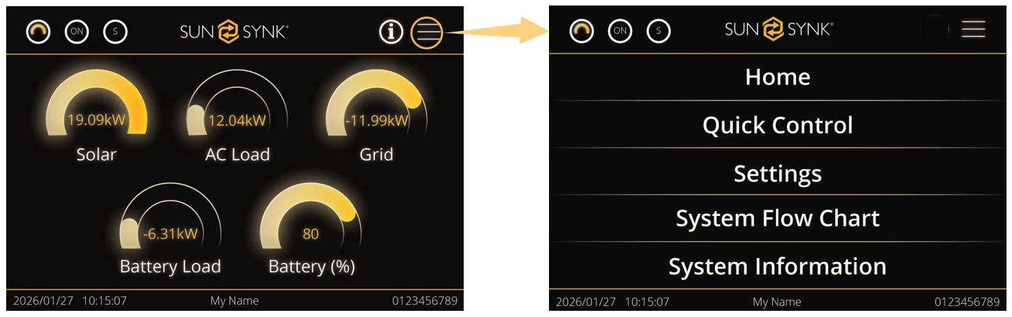
The Menu Screen provides users with access to the core settings and configuration options of the Three-Phase LP IP65 Inverter. From here, users can navigate to important sections like System Setup, Quick Control, and Settings. This screen is essential for managing the system’s functionality and viewing system diagnostics.
Access this screen by tapping the “Menu” icon on the Home Screen.
MENU OPTIONS
Once you tap the Menu icon, a dropdown screen appears with the following options:
- Home: Returns you to the Home Screen where you can view real-time system status and power flow information.
- Quick Control: Provides fast access to commonly used control options and system settings.
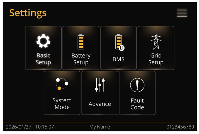
- Settings: Opens the Settings Menu for detailed configuration options, including battery, grid, inverter settings, and more.
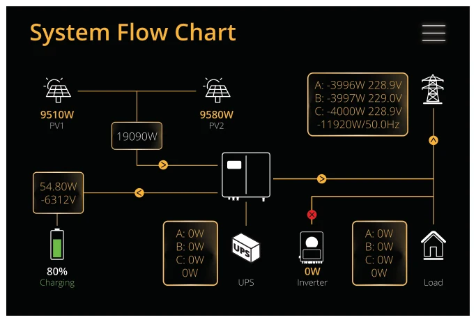
- System Flow Chart: Displays system flow chart that shows the power generation and distribution process in a graphical format. This is helpful for understanding how energy flows between the inverter, battery, grid, and loads.
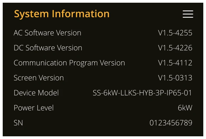
- System Information: Provides detailed information about system, including version, model, and SN.
Menu | Quick Control
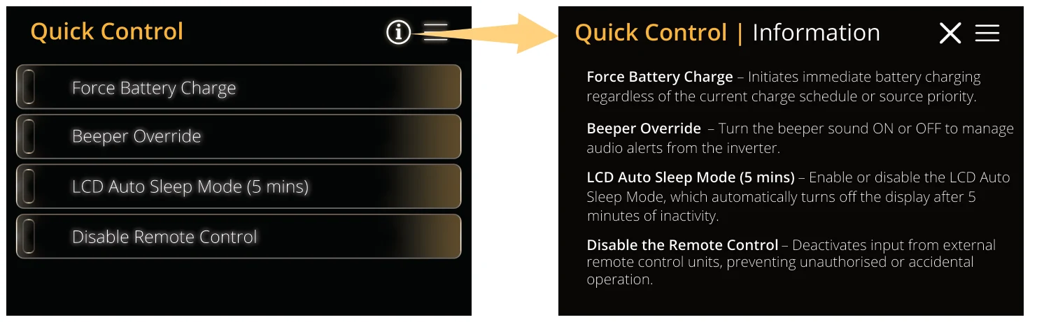
The Quick Control screen provides immediate access to certain inverter functions, allowing users to quickly toggle settings for specific operational needs. This screen enables quick adjustments to the system, ensuring efficient performance and control when needed.
Access this screen by tapping the “Quick Control” option in the Menu.
Menu | Settings
The Settings screen provides access to various configuration and diagnostic menus. Each menu item allows users to navigate to specific areas of the system to customize settings, perform system checks, and adjust operational parameters. This screen is critical for in-depth system management.
Access this screen by tapping the “Settings” option in the Menu.
Menu | System Flow Chart
The System Flow Chart screen provide visual representations of how energy flows within the system, tailored to specific installation configurations. This chart allow users to understand and monitor how power is distributed among key components of the system, such as solar panels, batteries, inverters, and loads, under operating conditions.
Access this screen by tapping the Home screen icon or “System Flow Chart” option in the Menu.

Menu | System Information
The System Information screen provides detailed technical data about the inverter. This page is essential for diagnostics, support, and firmware compatibility verification.
You can access this screen by tapping the “System Information” option in the Menu.
Settings Page
The Settings Page provides users with direct access to a variety of system configuration options and diagnostic menus. This page serves as the hub for all advanced system settings, allowing users to quickly navigate to different sections for in-depth system management.
Access this page by tapping the “Settings” option from the Menu.
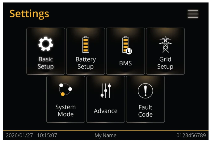
What you can do from this page:
- Basic Setup Page: Configure initial system settings, including date & time, name and display.
- Battery Setup Page: Adjust battery settings such as charge limits and voltage.
- BMS Page: View battery information including charging, and discharging status.
- Grid Setup Page: Configure grid settings, such as voltage and frequency.
- System Mode Page: Select operating modes and timer settings.
- Advance Page: Access advanced system configurations.
- Fault Code Page: Access system error logs and fault codes.
Basic Setup
The Basic Setup screen allows users to configure basic system settings for the inverter.
Access this page by tapping the “Basic Setup” option in the Setup Menu.

What you can do from this page:
- Set Time & Date: Adjust the system's time and date settings.
- Set System Name: Customize the name of the inverter system.
- Set Display Functions: Configure display brightness.
- Reset: Perform factory reset on the inverter.
Basic Setup | Time & Date
The Time & Date screen allows users to configure the current system time and date. This is essential for accurate system logging, scheduling, and synchronization with other devices.
Access this page by tapping the “Time & Date” option under Basic Setup.
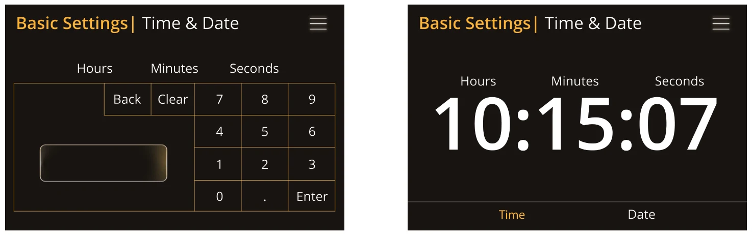
Time Settings:
This screen allows you to set the hours, minutes, and seconds for the clock.
Important: You must set the Hours, Minutes, and Seconds one at a time. This screen is used for each step, but you cannot enter the full time (HHMMSS) at once.
- From the previous menu, select the value you want to change (e.g., Hours).
- On the keypad screen, enter the value for the hour.
- Press the ‘Select’ button to save.
- Repeat this process for Minutes and Seconds until the correct time is set.
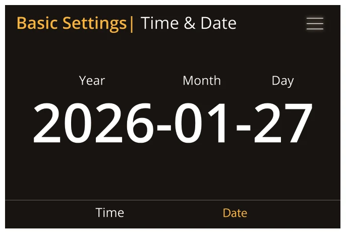
Date Settings:
This screen displays the current date in a YYYY-MM-DD format and is used to change the year, month, and day.
Important: You must set the Year, Month, and Day individually. The system will take you to a keypad screen for each step.
To set the date, tap on the Year field. You will be taken to the numeric keypad screen.
- Enter the full four-digit year (e.g., 2025).
- Press ‘Select’ to save.
Repeat this process for Month and Day until the correct date is set.
Basic Setup | Name
The Name Setup screen allows users to set or change the system name. This name can be used to identify the inverter in the system’s settings or for network identification.
Access this page by tapping the “Name” option under Basic Setup.
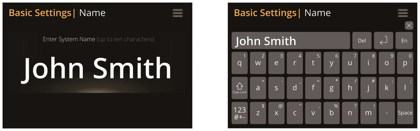
What you can do from this page:
- Set a unique system name (up to ten characters).
- Tap to begin entering the name.
- Use the on-screen keyboard to input the name.
- The system supports both letters and numbers.
- Select characters using the arrow keys below the on-screen keyboard.
- If necessary, edit or clear the existing name by using the keyboard controls.
Basic Setup | Display
The Display Setup screen allows users to configure the brightness of the screen.
Access this page by tapping the “Display” option under Basic Setup.

What you can do from this page:
- Set the Display Brightness: Adjust the brightness level of the LCD display from 0% to 100%.
Basic Setup | Reset

What you can do from this page:
- Factory Reset: Reset the inverter to default settings.
Battery Setup
The Battery Setup page allows users to configure key settings related to the battery type, charging parameters, and shutdown settings.
Access this page by tapping the “Battery Setup” option in the Setup Menu.

What you can do from this page:
- Set Up the Battery Type: Configure the type of battery used (e.g., lithium, lead-acid, etc.).
- Set Up the Battery Charge: Adjust the charging parameters, including charge voltage and current settings.
- Set Up the Shut Down: Configure shutdown parameters for the battery.
Battery | Type
The Battery Type page allows users to select the appropriate battery type for their system, based on the battery configuration and the type of Battery Management System (BMS) used.
Access this page by tapping the “Type Options" under Battery Setup.
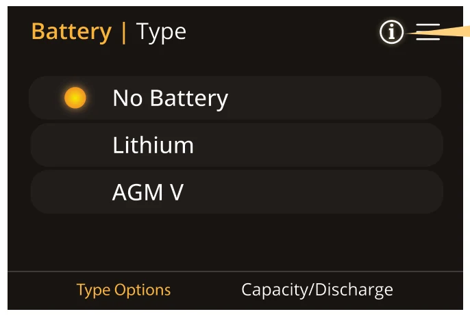
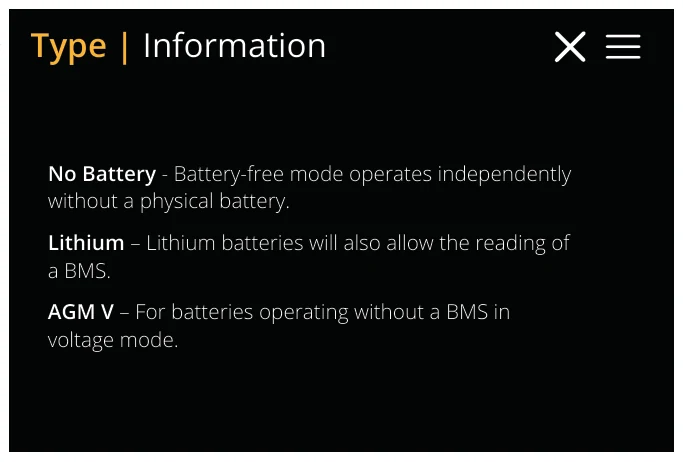
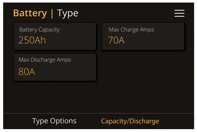
After select the appropriate battery type, access the “Capacity/Discharge" tab under Battery Setup. This page allows users to set up key parameters for battery capacity, charge/discharge current, and communication protocols.
What you can do from this page:
- Battery Capacity (Ah): For non-BMS-batteries the range allowed is 0-2000Ah, while for lithium-ion, the inverter will use the capacity value of the BMS.
- Charge/Discharge Amps: The Max battery charge/discharge current (120/130A for 6kW model, 150/180A for 8kW model, 180/220A for 10kW model, and 220/260A for 12kW model).
Battery | Charge
The Battery Charge Configuration page allows users to set the charging parameters of the battery.
Access this page by tapping the “ Battery Charge” option under Battery Setup.
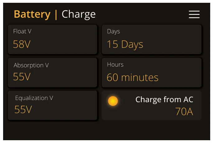
The Battery Charge Parameters page allows users to configure specific charge settings for the battery, such as charge rate, float voltage, absorption voltage, and equalization voltage.
What you can do from this page:
- Equalization V: Sets the equalizing voltage to help remove sulphate crystals from lead-acid batteries. For AGM batteries, the standard value is 55.00V.
- Float V: Defines the voltage used to maintain the battery once fully charged. For AGM batteries, this is typically 58.00V.
- Days: Refers to the interval (in days) between each equalisation charge cycle. This value can be adjusted by the user to control the frequency of equalisation charging.
- Hours: Refers to the duration (in hours) of each equalization charge cycle. This value is adjustable, allowing users to specify how long the equalization charge should run.
- AC Charge Amps: Indicates that the battery is currently set to charge from an AC source.
Users can manually set or adjust both the interval (in days) and duration (in hours) of the equalization charge, according to system requirements or maintenance schedules.
Do not alter these settings too often on the same battery, as it may damage the battery.
Generator Connection
A generator may be connected to the grid input.
The inverter treats generator input as grid power. Important: In this case, ensure that all power is used for Load only and is not exported, as this could damage the generator.
The generator must be capable of supplying both the load current and battery charging current simultaneously.
Battery | Shut Down
The Battery Shut Down page allows you to set the thresholds for when the inverter should shut down, alert the user about low battery, or restart. These settings ensure proper battery management and prevent excessive discharge that could harm the battery.
Access this page by tapping the “Shut Down” option under Battery Setup.
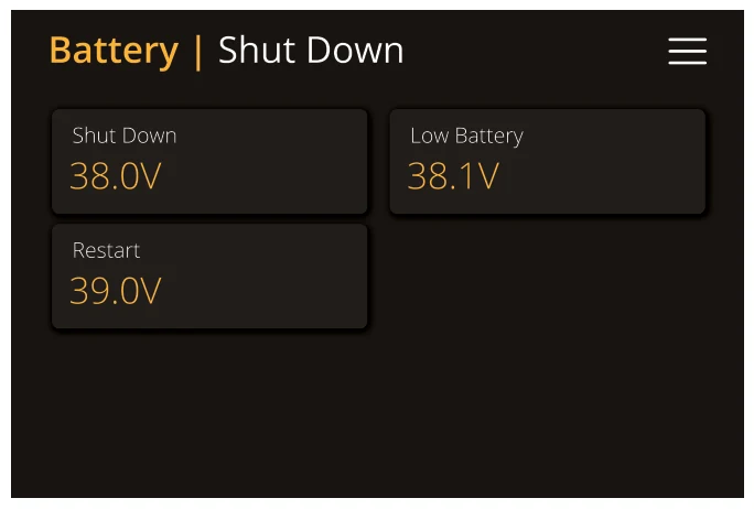
What you can do from this page:
- Shut Down: This setting indicates that the inverter will shut down if the battery voltage falls below 38.0V.
- Low Battery: This setting triggers an alarm when the battery voltage drops below 38.1V.
- Restart: The inverter will restart the AC output when the battery voltage reaches 39.0V, ensuring proper functioning once the battery has been sufficiently recharged.
Activating Shutdown causes the inverter to enter standby mode. It does not fully turn off the inverter. The total shutdown occurs only when battery voltage drops below 19V.
The voltage shown on the Sunsynk Inverter varies depending on whether the inverter is charging or discharging the batteries.
| Battery Level | Discharge Voltage | Charge Voltage |
|---|---|---|
| Fully Charged | 50.54V (x4 = 202.16V) | 58.80V |
| 75% Charged | 49.60V | 54.80V (Discharge Mode) |
| 50% Charged | 48.60V | 50.80V (Discharge Mode) |
| 25% Charged | 48.00V | 48.00V (Discharge Mode) |
| 0% (Shutdown Trigger) | 47.50V | - |
*The table shows approximate values for a 48V system. For lithium batteries, values will differ slightly.
*For best performance and battery life, avoid setting the cut-off voltage too low.
The Sunsynk inverter is compatible with AGM Lead Acid and Lithium Battery Banks. Below is a brief explanation of each:
- AGM (Absorbent Glass Mat):
- A sealed lead-acid battery design with internal mats that absorb and immobilise electrolyte.
- Ideal for deep-cycle applications.
- Lithium (LiFePO 4 ):
- Longer lifespan and high efficiency.
- Must use manufacturer-defined charging profiles.
STATE OF CHARGE
- Bulk Stage:
- Delivers a large current to restore most of the battery’s capacity (~80%).
- Continues until voltage reaches the set absorption level.
- The proper charger supplies current based on the battery's Ah rating.
- Absorption Stage:
- Voltage is held at a higher level to complete the final 20% of the charge.
- Required to fully saturate the battery and avoid sulfation.
- Typical AGM absorption voltage: 14.1V – 14.8V DC (depending on model).
- Float Stage:
- Voltage is reduced to 13.0V – 13.8V DC to maintain the charge without overcharging.
- Ensures battery is ready for use while preserving lifespan.
- Equalization (Lead-Acid only):
- Periodically increases voltage above normal levels to desulphate the battery plates.
- Not used with lithium batteries.
- AGM batteries benefit from this occasionally if recommended by the manufacturer.
Battery Management System (BMS)
After installing a lithium battery, verify that communication between the battery and the inverter is working properly. To do this:
- Tap the BMS icon on the screen.
- Check whether the battery information appears correctly.
If no data or incorrect data is displayed (as shown in the examples below), a communication error has occurred.
If a BMS communication issue is detected:
- Check that the data cable is the correct type (e.g., RS485, CAN, or manufacturer-specific).
- Ensure the cable is connected properly into the appropriate BMS communication port.
Some battery manufacturers use communication protocols other than RS485 (such as CAN). Refer to the battery manual for exact connection requirements.
It is crucial to refer to the manuals that manufacturers produce for their batteries. That way, the chance of errors occurring during installation is significantly reduced. The following batteries are compatible with Sunsynk Three-Phase LP IP65 Inverter:
- SUN-BATT-5.32
- SUNSYNK-L5.3
- L051069-A
Grid Setup
The Grid Setup page allows users to configure grid-related parameters, including connection type, protection settings, and advanced reactive power features.
Access this page by tapping the “Grid Setup” icon under the Settings menu.

What you can do from this page:
- Set up the Grid Type functions.
- Set up the Grid Connection.
- Set up the Inverter Protection.
- Unlock Grid Settings. The inverters grid settings are automatically locked, so if you need to make changes to the grid settings you will need to select this, and it will ask for the password code. The password is 7777.
Grid | Type
The Grid Type menu allows you to configure how the inverter operates in relation to your local grid standard. You can set the grid compliance mode, grid connection type, and the inverter's output voltage.
Access this page by selecting "Type" from the Grid Setup menu.

Grid Mode Selection
- Use the arrow keys to select a mode. Follow your local grid code and choose the matching grid standard from the menu. *G100: Please ensure the inverter is set to G99/G100 for compliance with local regulations.
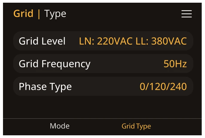
Grid Type
- Set the Grid Level.
- Set the Grid Frequency.
- Set the Phase Type.
Grid | Connect
The Grid Connect page allows you to configure the parameters for the inverter's connection to the grid, including the allowed voltage and frequency ranges and reconnection time.
Access this page by selecting "Connect" from the Grid Setup menu.
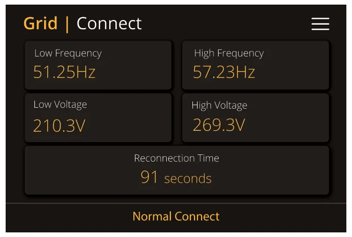
Grid Connection Settings (First Time Connect)
- Set the allowed grid voltage/frequency range for when the inverter first connects to the grid.
- Set the reconnection time.
Grid | Inverter Protection
The Inverter Protection page allows you to set the voltage and frequency protection points for the inverter. This helps ensure that the inverter shuts down or disconnects if the grid's parameters fall outside acceptable ranges, protecting both the inverter and connected components.
Access this page by selecting "Inverter Protection" from the Grid Setup menu.
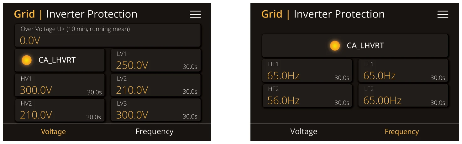
Voltage Protection Settings
Frequency Protection Settings:
- Overvoltage U > (running mean value over 10 minutes).
- CA_LHVRT: Configuration of over voltage and undervoltage of the grid power. Once enabled, LV1, LV2, LV3, HV1, and HV2 are all effective, and when disabled all are ineffective.
- HV1 (Over Voltage Protection Level 1): Set the level 1 overvoltage protection point. It triggers when the grid voltage exceeds the defined value.
- HV2 (Over Voltage Protection Level 2): Set the level 2 overvoltage protection point.
- LV1 (Under Voltage Protection Level 1): Set the level 1 undervoltage protection point. The inverter disconnects if the grid voltage falls below this level.
- LV2 (Under Voltage Protection Level 2): Set the level 2 undervoltage protection point.
- LV3 (Under Voltage Protection Level 3): Set the level 3 undervoltage protection point.
- CA_LHVRT: Configuration of over frequency and under frequency of the grid power. Once enabled, LF1, LF2, HF1, and HF2 are all effective, and when disabled all are ineffective.
- HF1 (Over Frequency Protection Level 1): Set the level 1 over frequency protection point. This setting will disconnect the inverter if the grid frequency exceeds the threshold.
- HF2 (Over Frequency Protection Level 2): Set the level 2 over frequency protection point.
- LF1 (Under Frequency Protection Level 1): Set the level 1 under frequency protection point.
- LF2 (Under Frequency Protection Level 2): Set the level 2 under frequency protection point.
System Mode
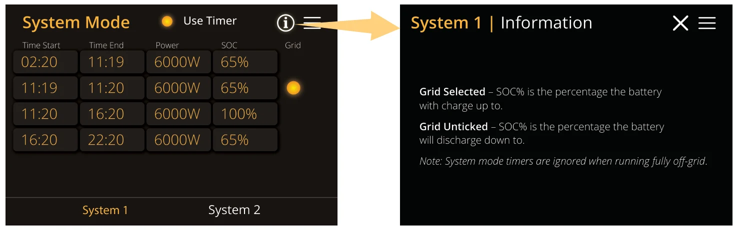
Example:
- During 02:20-11:19, when the battery SOC is higher than 65%, the inverter will discharge the battery until the SOC reaches 65%. The power output will be capped at 6000W.
- During 11:19-11:20, when the battery SOC is lower than 65%, the inverter will use the grid to charge the battery until the battery SOC reaches 65%. It will draw up to 6000W of power.
- During 11:20-16:20, when the battery SOC is lower than 100%, the inverter will not discharge the battery.
- During 16:20-22:20, when the battery SOC is higher than 65%, the inverter will discharge the battery until the SOC reaches 65%.
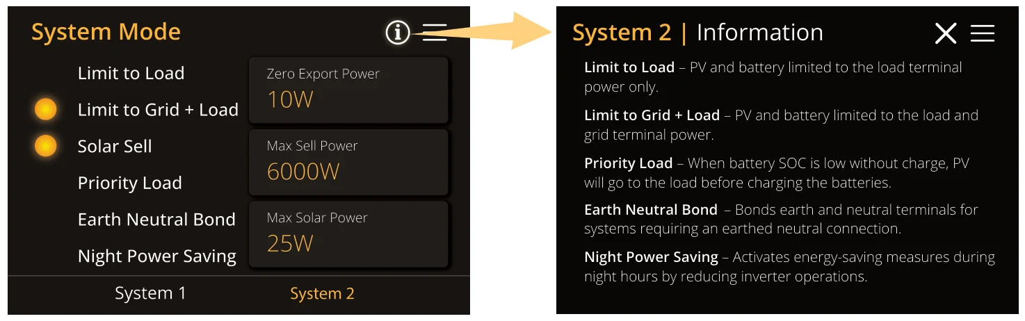
Advance | Multi-Inverter
This screen allows you to configure multiple Sunsynk inverters to work together in parallel. Use this page when installing a system with more than one inverter connected on the same AC bus.

What you can do from this page:
- Enable Parallel Mode: Switch ON the parallel function so the inverter can work with others in the system.
- Primary or Secondary Role: Select whether this inverter acts as master or slave on the communication bus.
- Set Modbus SN: Assign a unique Modbus Serial Number to this inverter for communication. Each inverter in the parallel system must have a different number.
The Three-Phase LP IP65 can operate as a standalone unit or in a parallel configuration to increase power capacity.
PARALLEL SYSTEM LIMITS
- Up to 3 inverters (1 Master + 2 Slaves).
INSTALLATION GUIDELINES
- Battery bank: All batteries must be connected in parallel.
- Cabling: Use a minimum 50mm² cable with fuse isolators per inverter.
- Protection: Each inverter requires:
- Surge-protected fuse isolator.
- RCD for each inverter.
- Changeover switch (if powering main loads during outages).
- CT coils: Only connect to the Master inverter.
- Communication: Use RJ45 cables to connect the inverters.
- Cables are bidirectional (no IN/OUT).
- Max length between units: 2 metres.
- Each inverter must have a unique Modbus SN.
- Ensure all inverters have the same firmware version before configuring.
- Isolate each inverter’s load output with individual load breakers before connecting them to the common parallel breaker.
- Only enable breakers after all units are programmed and tested.
- For three-phase systems, verify phase rotation is clockwise before powering on.
To ensure the proper functioning of the parallel operation, it is important first to establish the work mode for both the Master and Slave inverters and then make the necessary wiring connections.
If you make the connection prior to changing the work mode, an F15 error will be displayed on the Fault Codes page. In the event of this error, please maintain the connection and proceed to the settings to modify the work mode as presented above, and wait approximately 3-4 minutes. After that, the device should return to its normal working condition, with the error cleared.
TROUBLESHOOTING & FAQS
Q1: What is the sequence to install/connect/commission?
First of all, leave the main supplies off. Next, connect all communication cables, set up all LCDs and then, turn on the main supplies.
Q2: What are the indications that the communication and the system are OK or not?
Parallel errors will be shown as fault F29 and F41 on the display.
Q3: What are the consequences of not setting one inverter in a parallel mode?
It can damage the inverter.
Q4: What are the consequences of having more than one Master Inverter or having no inverter set as ‘Master’?
It can damage the inverter.
Q5: What are the consequences for setting A, B, or C phases wrong while in parallel mode?
It can damage the inverter. Recommend checking the phase rotation with a meter before switching on.
Q6: What are the consequences of factory resetting, power cycling, or firmware updating one inverter in a parallel system? It can damage the inverter. Prior to factory reset or firmware update, the inverters must be isolated from each other.
Q7: What consequences for changing ALL/ANY settings while operating in parallel mode?
It can damage the inverter.
For support and resources (including training videos), visit: www.sunsynk.com
Advance | Others
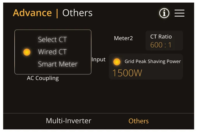
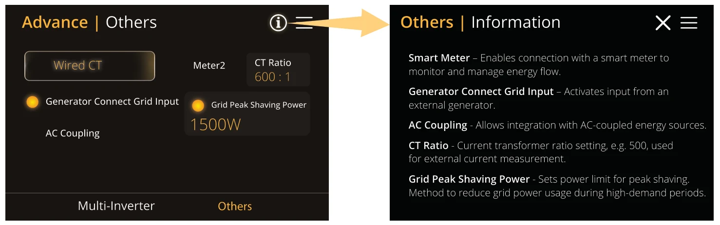
The Others tab includes additional advanced system features, such as smart meter configuration, grid interaction parameters, and special operating modes.
| NO. | Remote CT (Smart Meter) |
|---|---|
| 1 | 12V |
| 2 | 12V |
| 3 | 485-B |
| 4 | 485-B |
| 5 | 485-A |
| 6 | 485-A |
| 7 | GND_485 |
| 8 | GND_485 |
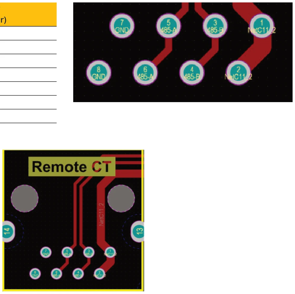
Pinout Connections for BMS
| NO. | BMS |
|---|---|
| 1 | N/A |
| 2 | N/A |
| 3 | N/A |
| 4 | CANH |
| 5 | CANL |
| 6 | N/A |
| 7 | N/A |
| 8 | N/A |
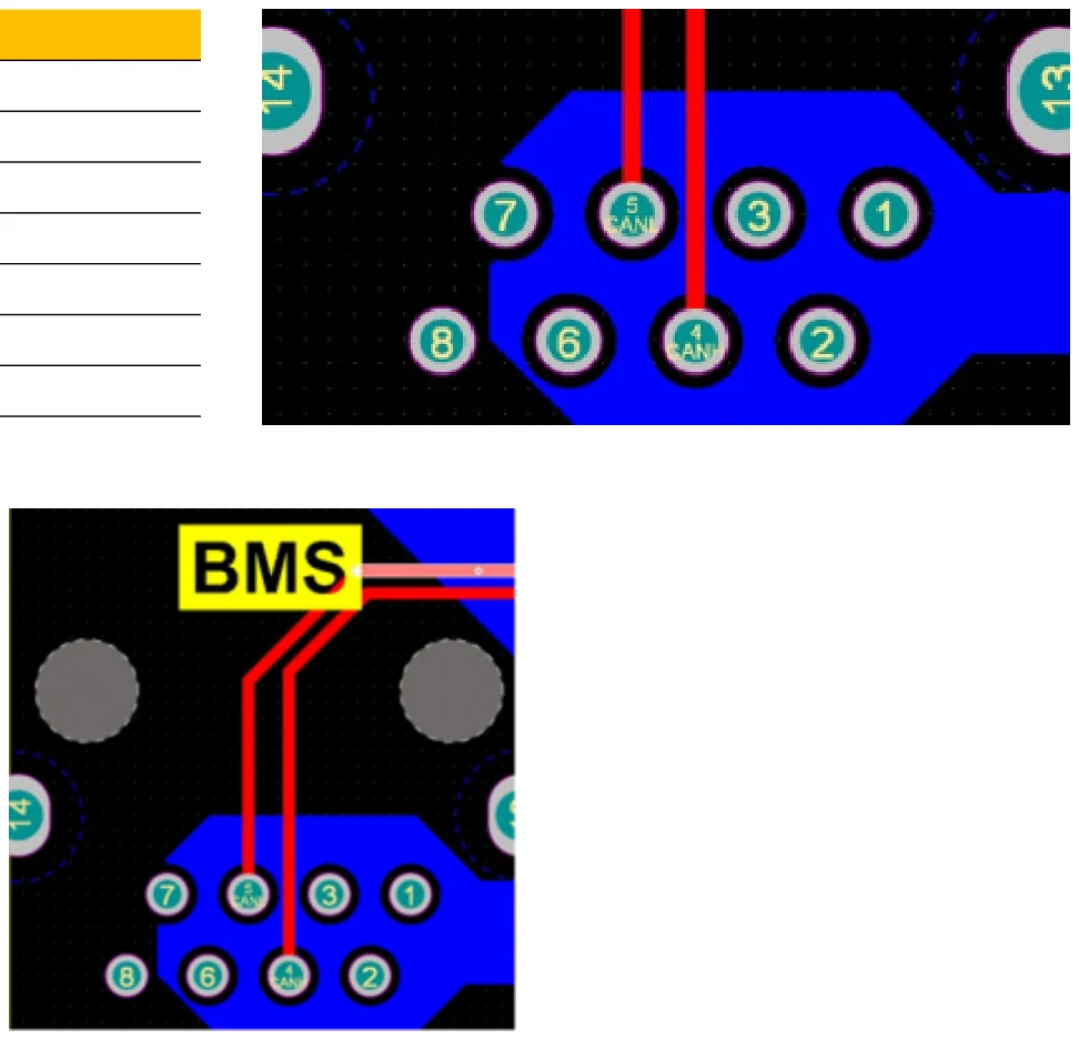
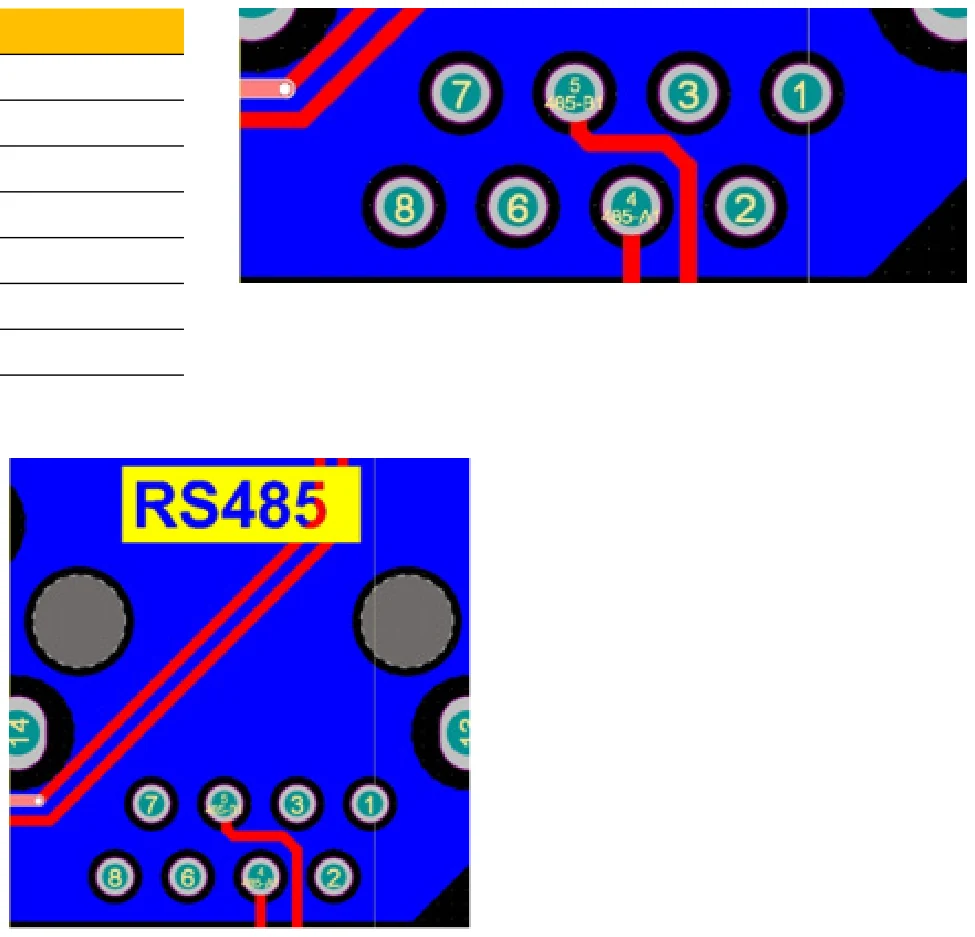
Pinout Connections for RS485
| NO. | RS485 |
|---|---|
| 1 | N/A |
| 2 | N/A |
| 3 | N/A |
| 4 | RS485-A1 |
| 5 | RS485-B1 |
| 6 | N/A |
| 7 | N/A |
| 8 | N/A |