Fault Codes
The Fault Codes page allows users to review historical fault events recorded by the inverter. Each entry displays a fault code, description, date, and time the fault occurred. This function is helpful for diagnosing system issues, especially when troubleshooting installation or runtime errors.
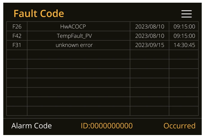
What you can do from this page:
- View all recorded system faults in a list format.
- Check the fault code reference to understand the nature of the fault.
- Note the date and time to correlate events with grid conditions or system actions.
- Use the fault code to find troubleshooting steps in the technical manual.
The device’s status is primarily determined by the LED indicator light and whether the error reporting icon on the main page is displayed as OFF.
If any of the fault messages listed in the following table appear on your inverter and the fault has not been removed after re-starting, please contact your local vendor or service centre. The following information is required:
1. Inverter serial number.
2. Distributor or service centre of the inverter.
3. On-grid power generation date.
4. The problem description (including the fault code and indicator status displayed on the LCD) with as much detail as possible.
5. Owner’s contact information.
In order to give you a clearer understanding of the inverter's fault information, we will list all possible fault codes and their descriptions when the inverter is not working properly.
| Error Code | Display Error | Potential Method for Measurement and Fix |
|---|---|---|
| F07 | DC/DC_Softstart_Fault |
|
| F10 | AuxPowerBoard_Failure |
|
| F13 | Working mode change | Inverter work mode changed:
|
| F15 | Short circuit protecting | Short circuit fault:
|
| F18 | AC over current fault or hardware | AC slide over current fault:
|
| F20 | DC over current fault of the hardware | DC over current fault:
|
| F23 | AC leakage current is trans over current | Leakage current fault:
|
| F24 | DC insulation impedance failure | PV isolation resistance is too low:
|
| F26 | The bus bar is unbalanced |
|
| F29 | ECAN communicate |
|
| F30 | Load current exceeding |
|
| F34 | Over Load Protection |
|
| F35 | No AC grid |
|
| F37 | Battery activation overcurrent |
|
| F39 | DC-DC over current |
|
| F40 | DC over current |
|
| F41 | Parallel system stop |
|
| F42 | AC line low voltage | Grid voltage fault:
|
| F45 | AC line HIGH voltage |
|
| F47 | AC over frequency | Grid voltage fault:
|
| F48 | AC lower frequency | Grid frequency out of range:
|
| F55 | DC busbar voltage is high | User: External Battery Input voltage is high
|
| F56 | DC bus bar voltage is too low | Battery low voltage:
|
| F60 | Smoke alarm | When the smoke alarm is lifted, use the App to restart the inverter (Refer to the relevant content of the App user manual). |
| F61 | Bus one shutdown |
|
| F62 | DRMs0 stop | Reserved Error code |
| F63 | FAN Error |
|
| F64 | Heat sink high-temperature failure | Heat sink temperature is too high:
|
Debug
The Debug Screen provides advanced real-time diagnostic data from the inverter. This screen is useful for technicians and experienced users to observe live system status, flags, and performance readings.
To access the Debug screen:
- On the inverter’s front panel, press the following three buttons simultaneously for two seconds → Select + Up + Back.
The Debug screen will appear showing various internal parameters.
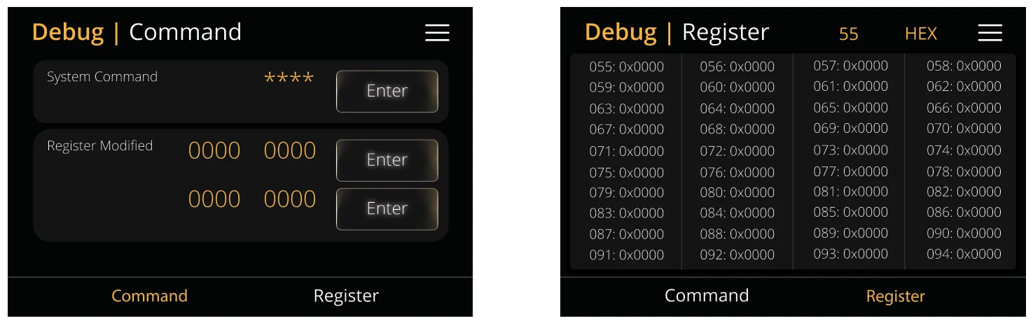
What You Can See on the Debug Screen:
- Live inverter flags and variables
- System operation statuses
- Voltage, power and frequency data
- Internal operational counters and state indicators
This screen is primarily intended for technical users. Most values are used for support diagnostics or firmware testing, and do not require user adjustment.