Installation
Selecting the Mounting Area
SM3.6kWLLL / SM3.6kWPLL
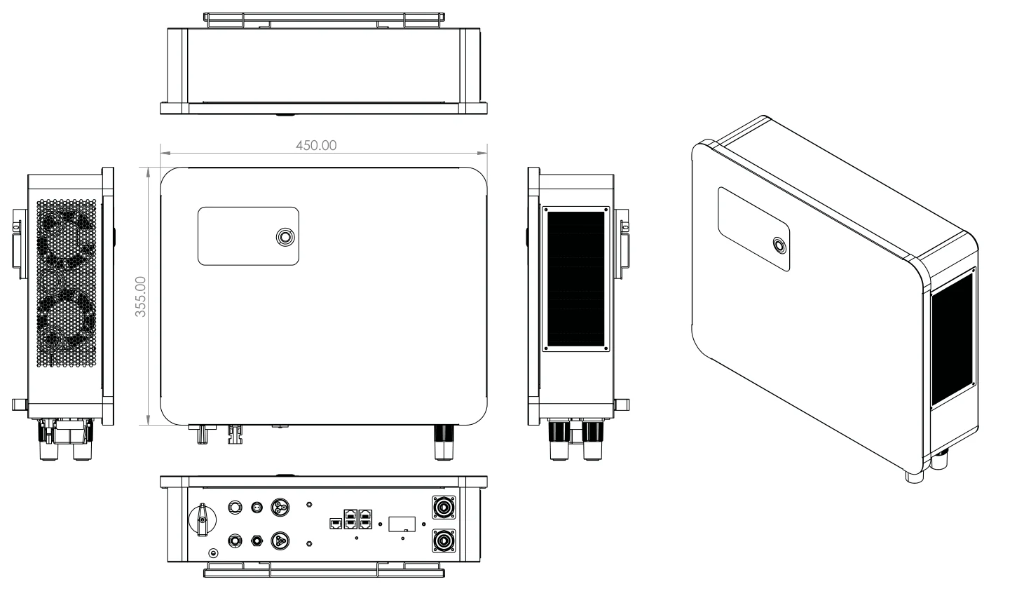
SM6.0kWLLL / SM6.0kWPLL
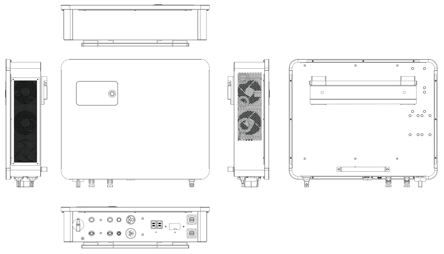
SM8.0kWLLL / SM8.0kWPLL
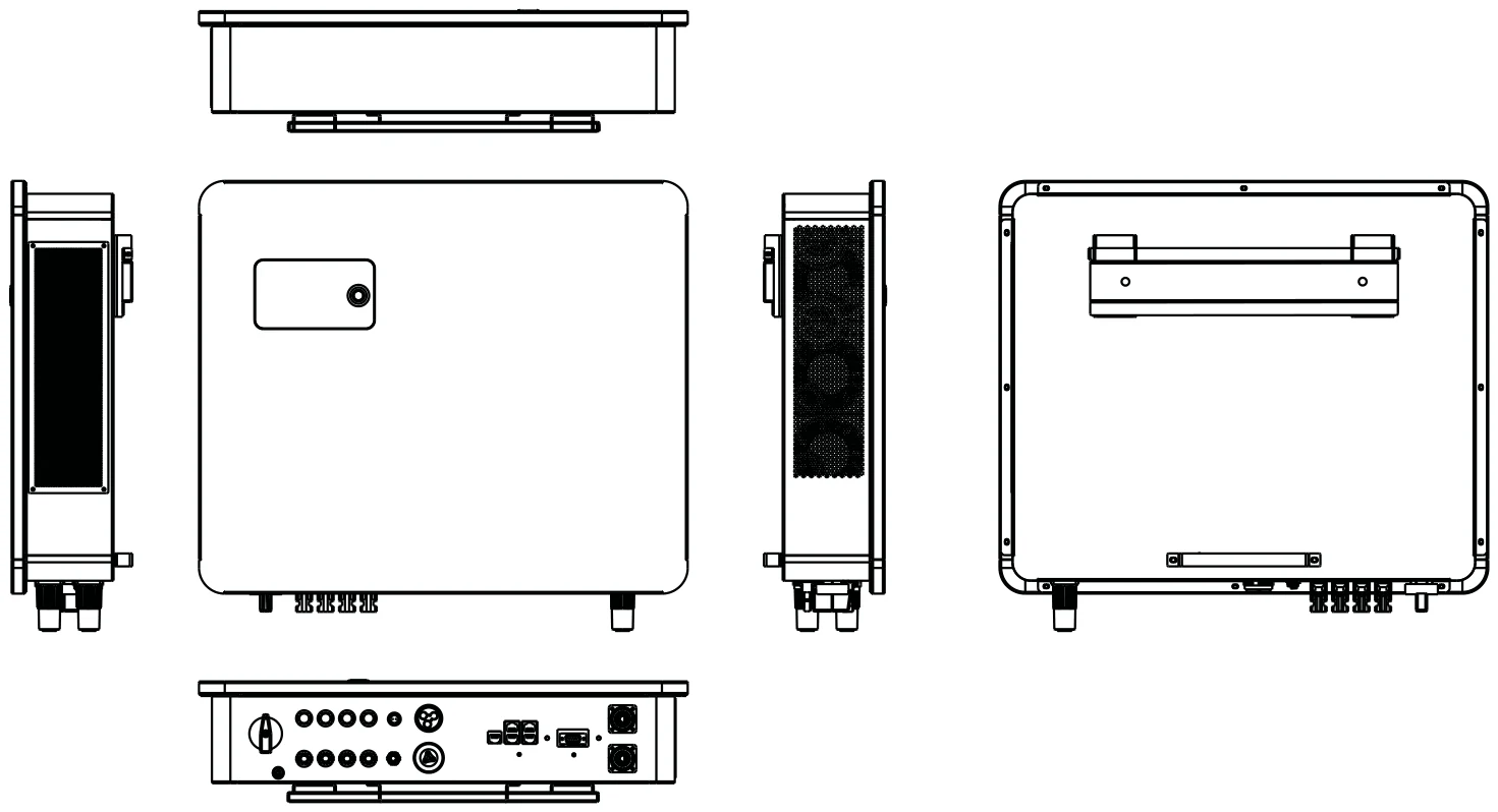
DO NOT INSTALL IN THE FOLLOWING AREAS:
- Areas with high salt content, such as the marine environment. It will deteriorate the metal parts and possibly lead to water / dampness penetrating the unit.
- Areas filled with mineral oil or containing splashed oil or steam such as in kitchens. This will deteriorate plastic parts of the unit, causing those parts to fail or allow water /damp to penetrate the unit.
- Areas that generate substances that adversely affect the equipment, such as sulphuric gas, chlorine gas, acid, or alkali. These can cause the copper pipes and brazed joints to corrode and fail to conduct electricity reliably.
- Areas that can cause combustible gas to leak, which contains suspended carbon-fibre, flammable dust or volatile inflammability such as paint thinner or gasoline.
- Areas where there may be gas leaks and where gas may settle around the unit, as this is a fire risk.
- Areas where animals may urinate on the unit or ammonia may be generated.
- High altitude areas (over 4000 metres above sea level).
- Environments where precipitation or humidity are above 95%.
- Areas where the air circulation is too low.
ALSO CONSIDER:
- Installing the indoor unit, outdoor unit, power supply cable, transmission cable and remote control cable at least 1 metre away from any television or radio receiver. This will prevent TV reception interference or radio noise. This will also prevent radio signal interference from external units that might interfere with the Wi-Fi or GSM monitoring.
- If children may approach the unit, take preventive measures so that they cannot reach and touch the unit.
- Install the indoor unit on the wall where the height from the floor is higher than 1600mm.
- For proper heat dissipation, allow a clearance of approximately 500mm to the side, 500mm above and below the unit and 1000mm to the front of the unit.
Mounting the Inverter
- Select a location that provides adequate support for the weight of the inverter.
- Install this inverter so that the LCD screen is eye-level for easy operation.
- An appropriate ambient temperature lies between -20 ~ 50°C for optimal operation. Battery charging temperature range lies between 0ºC ~ 50ºC.
- Ensure other objects and surfaces are outside of the recommended spaces (500mm each side / above and below / front) to guarantee heat dissipation and easy access to the wiring / cabling.
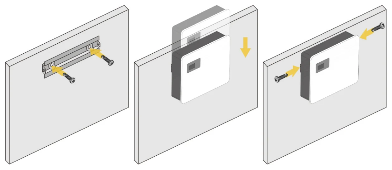
The inverter is heavy. Ensure the unit is handled carefully during installation, especially when mounting or removing it from the wall. Always use proper lifting techniques, and where possible, have two people assist with the mounting process to avoid injury.
Battery Cable Connection
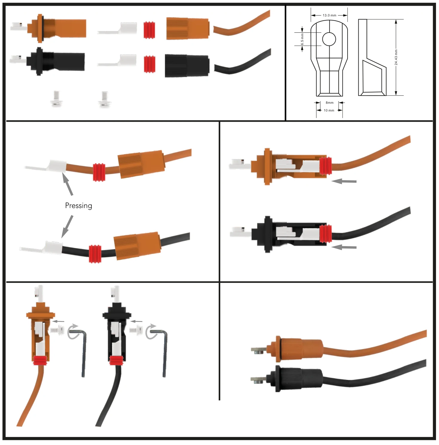
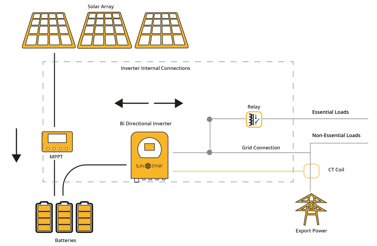
Flow Diagram
Connecting to the Mains / Grid
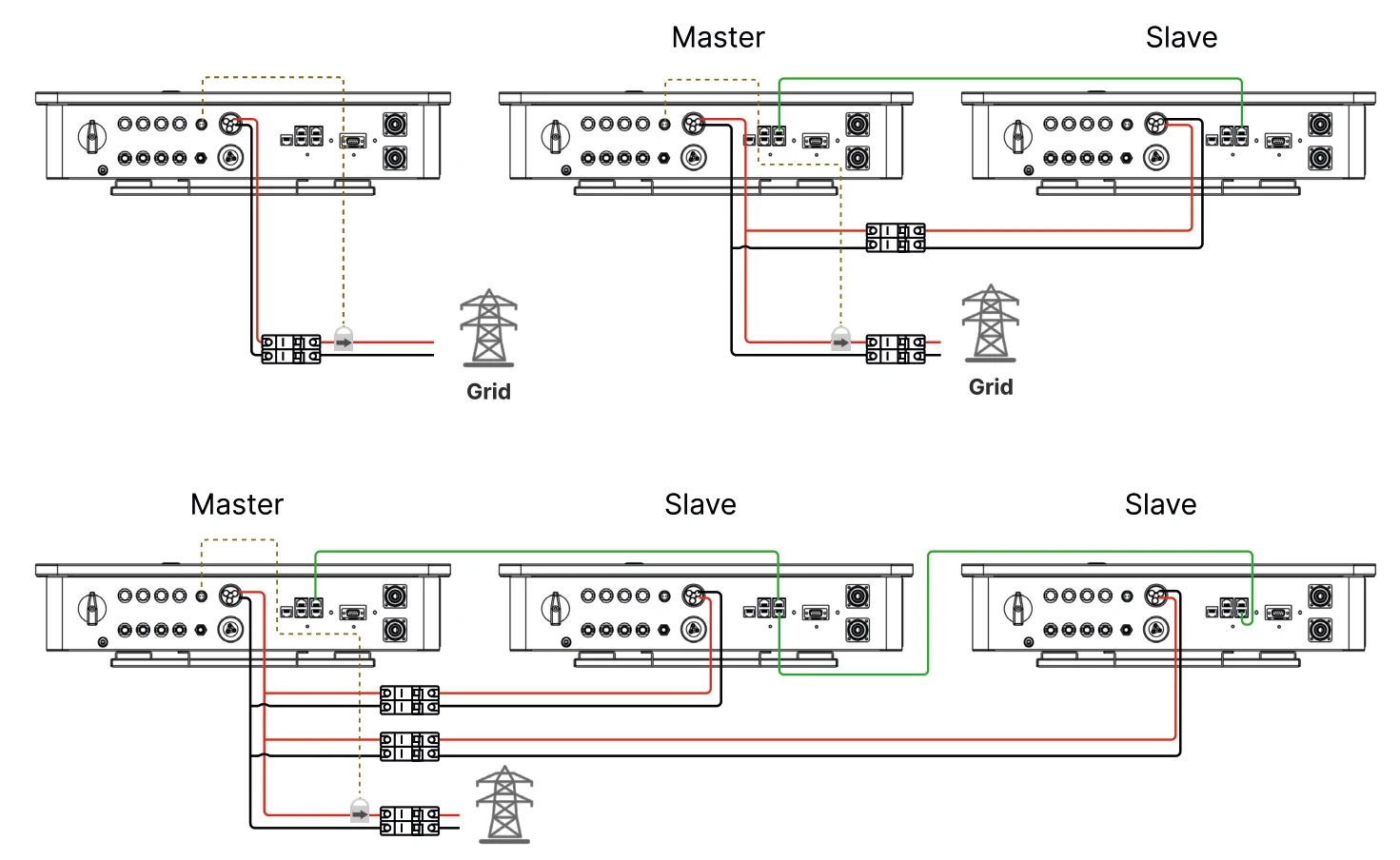
- Connect the Lynks Hybrid Inverter to the electrical grid via the grid ports, using a suitable RCD and a 30A fuse for the 3.6kW and 6kW models, and a 50A fuse for the 8kW model on the consumer board.
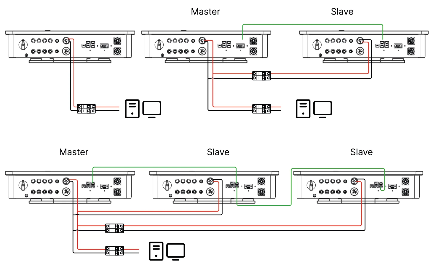
- Now, connect only the essential loads to the load ports (output) to a secondary consumer board, considering the maximum limit of 3.6/6/8kW according to the Lynks variant.
- Ensure the main consumer unit and the secondary consumer unit are correctly grounded to the Lynks.
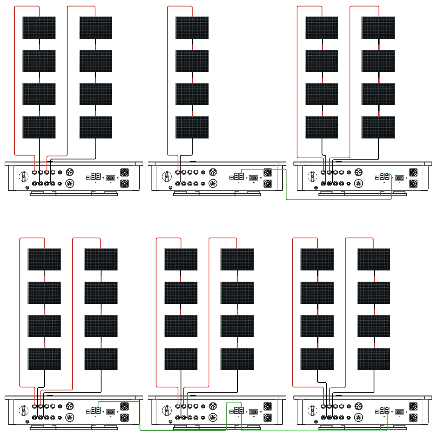
Wiring the PV Panels
- The Lynks 3.6kW model include one MPPT controller, supporting a maximum input current of 15A. The Lynks 6kW and 8kW models include two MPPT controllers, with the 6kW variant supporting a maximum input current of 30A (2 x 15A) and the 8kW variant supporting 46A (2 x 23A).
- Before connecting to PV modules, install a separate DC circuit breaker between the inverter and PV array.
- To avoid any malfunction, DO NOT connect any PV modules with possible current leakage to the inverter. For example, grounded PV modules will cause current leakage to the inverter.
- Also, the open-circuit voltage (Voc) of the PV modules does not exceed the maximum input voltage of the inverter. Also, the Voc of the PV array should be higher than the minimum starting voltage of the inverter.
- Connect the PV panels into the MC4 connectors.
CT Coil and Load Power Settings
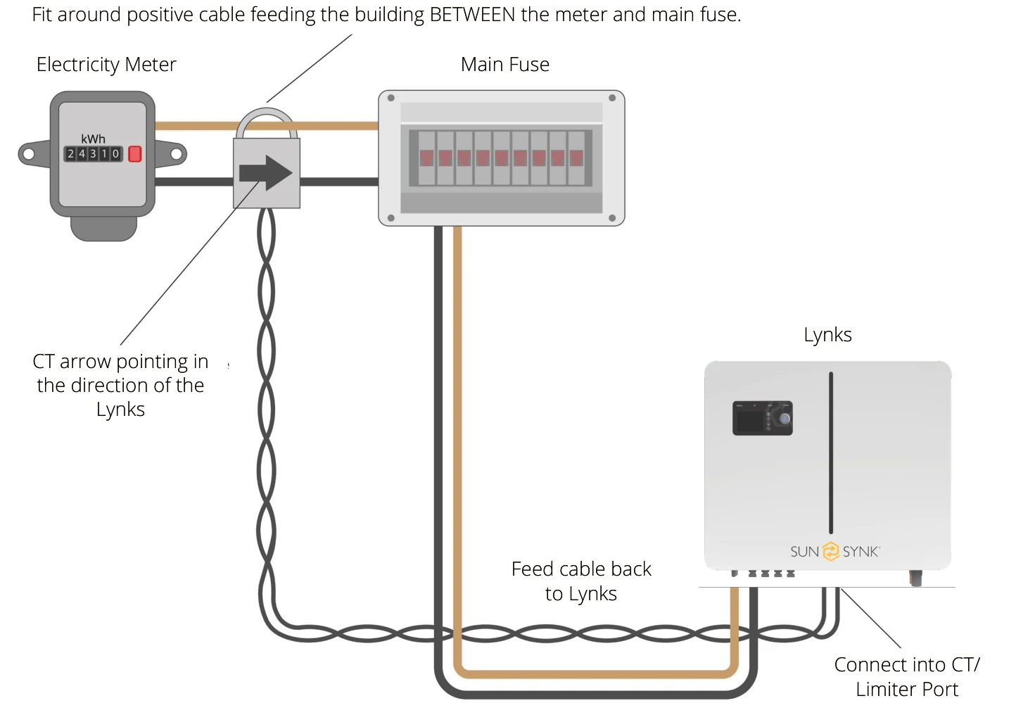
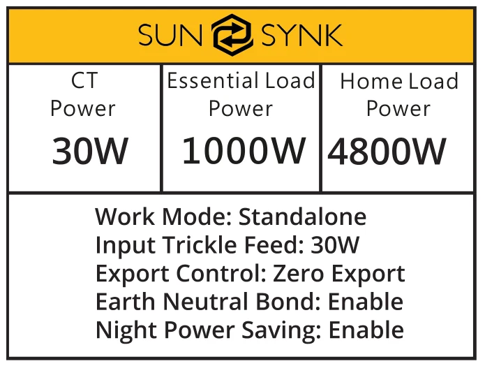
The CT coil is one of the most important parts of the Lynks. This device reduces the power of the inverter to prevent feeding power to the grid. This is also known as zero export.
- Fit the coil (sensor) around the live cable on the main fuse feeding the building and run the cable back to the inverter. This cable can be extended up to an extra 10m using a similar cable.
- Connect the other end of the CT coil into the inverter terminals marked as CT coil.
Always ensure the inverter is fully powered off and verified safe before connecting or extending the CT. Making connections while the inverter is live can cause severe damage and void warranties. Under no circumstances should live connections be made.
You can access the CT Coil Screen directly from the Home Screen by pressing the Home/Back button:
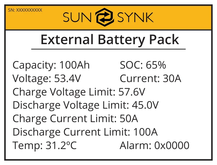
You can access the External Battery Pack page by pressing the Home/Back button again:
Parallel Operation
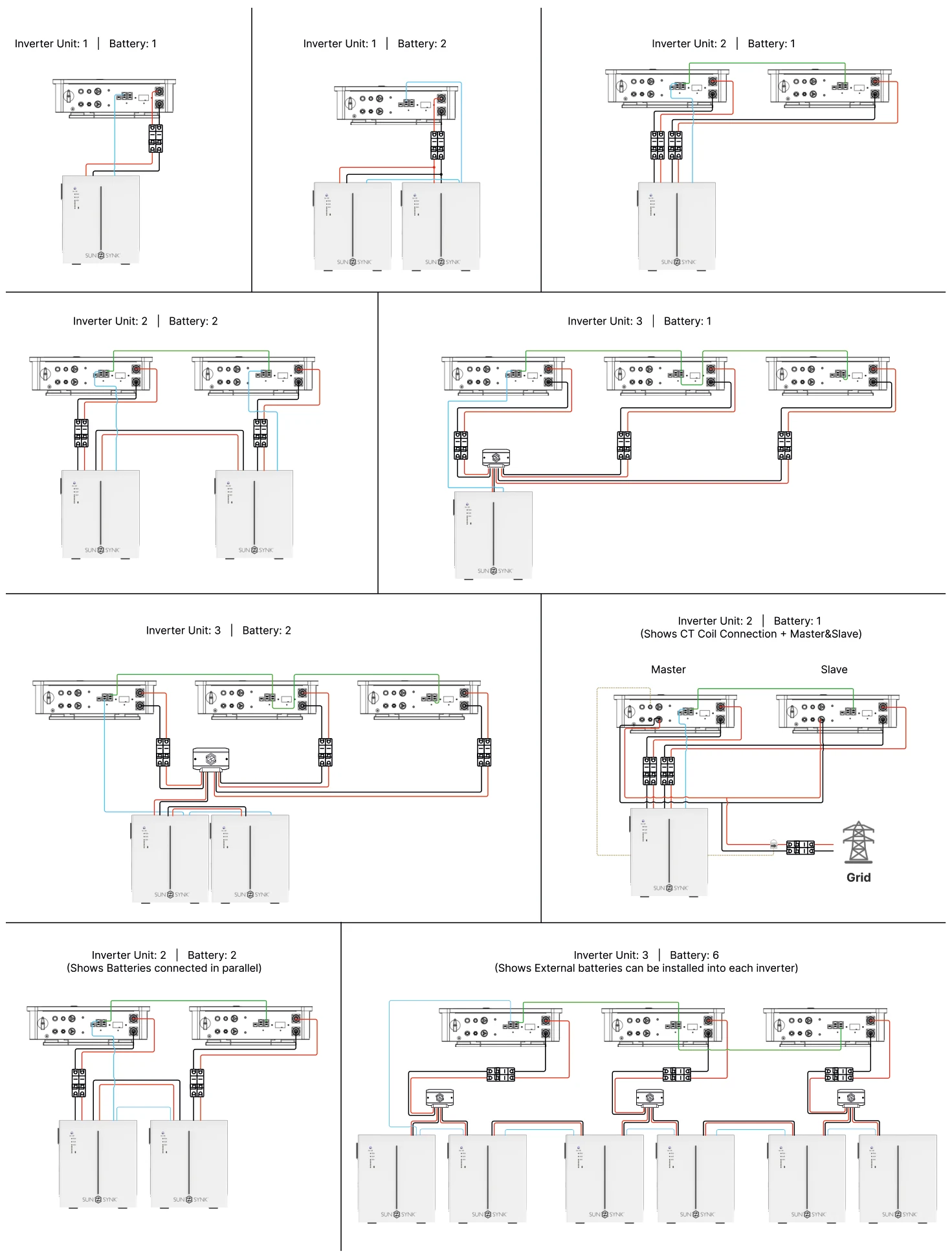
In order to connect Lynks inverters to operate in parallel, you need to set up the work mode configuration for each the inverter. Basically, you have to set which inverter will be the master and which will be the slaves, and then make the connections described in section External Battery and Parallel Connections.
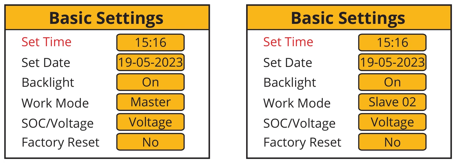
To ensure the proper functioning of the parallel operation, it is important first to establish the work mode for both the Master and Slave inverters and then make the necessary wiring connections. If you make the connection prior to changing the work mode, an F15 error will be displayed on the Fault Codes page. In the event of this error, please maintain the connection and proceed to the settings to modify the work mode as presented above, and wait approximately 3-4 minutes. After that, the device should return to its normal working condition, with the error cleared.
External Battery and Parallel Connections
SM3.6kWLLL / SM3.6kWPLL
SM6.0kWLLL / SM6.0kWPLL
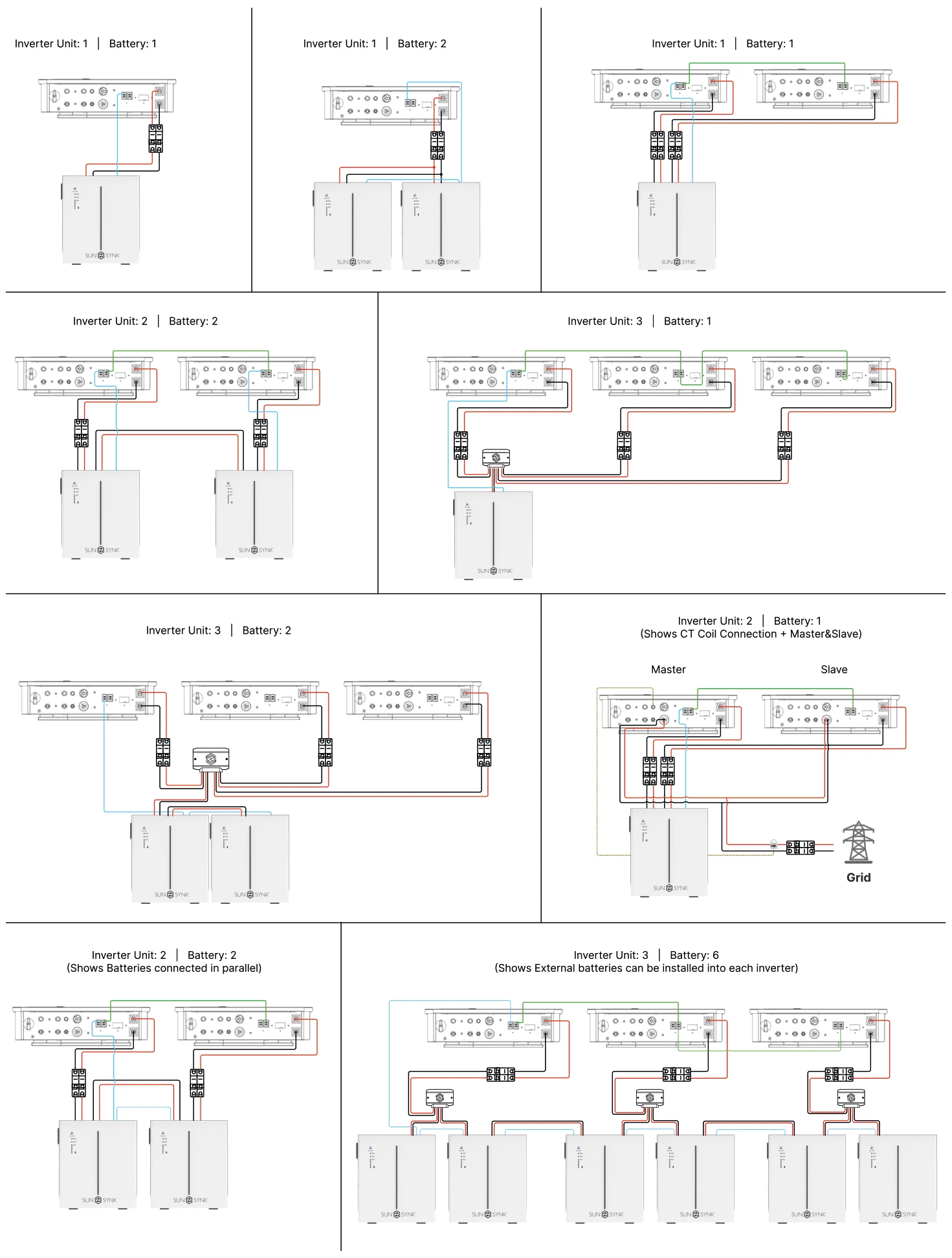
SM8.0kWLLL / SM8.0kWPLL
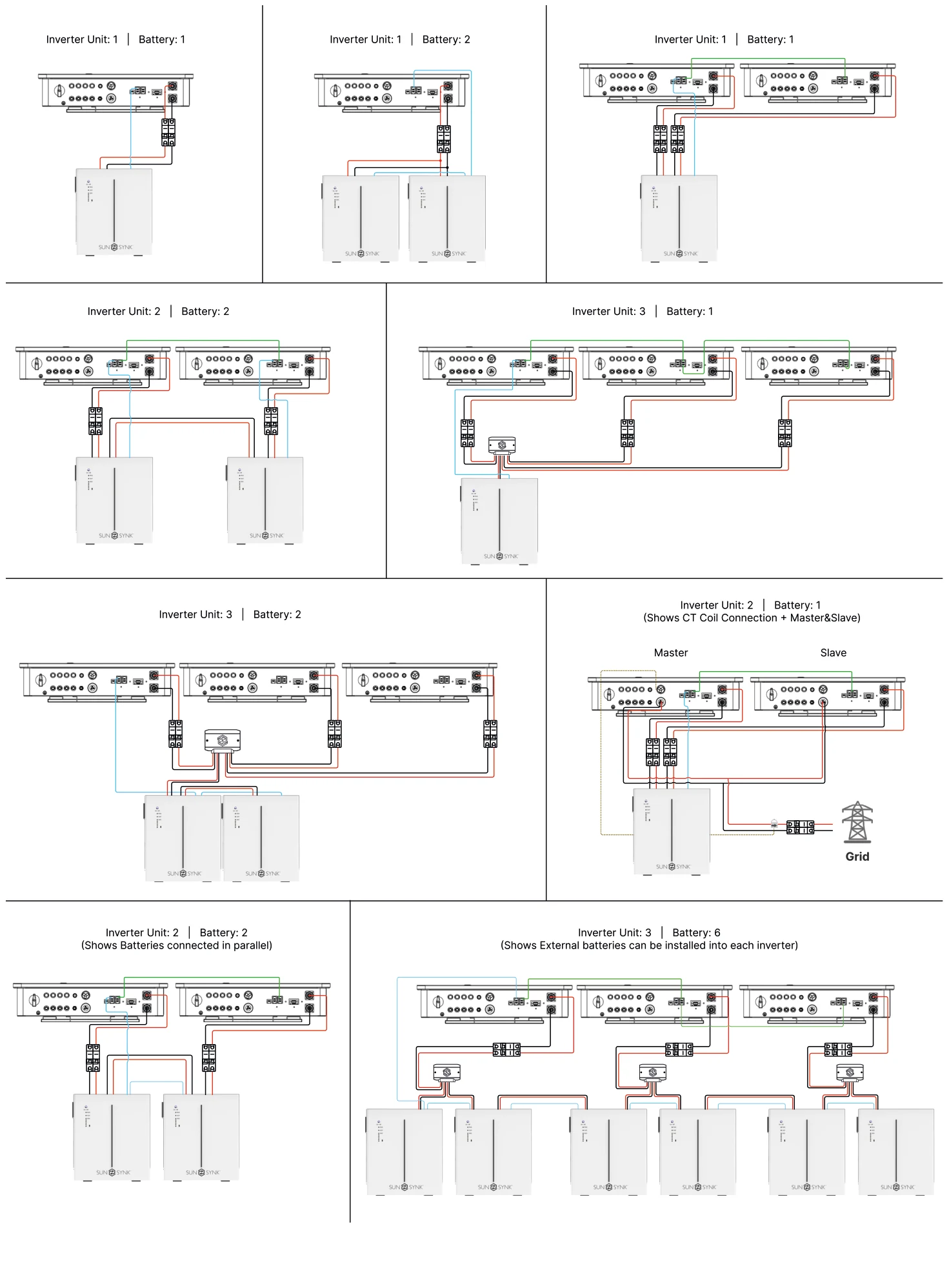
Load Connection
SM3.6kWLLL / SM3.6kWPLL
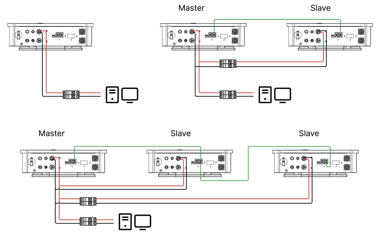
SM6.0kWLLL / SM6.0kWPLL
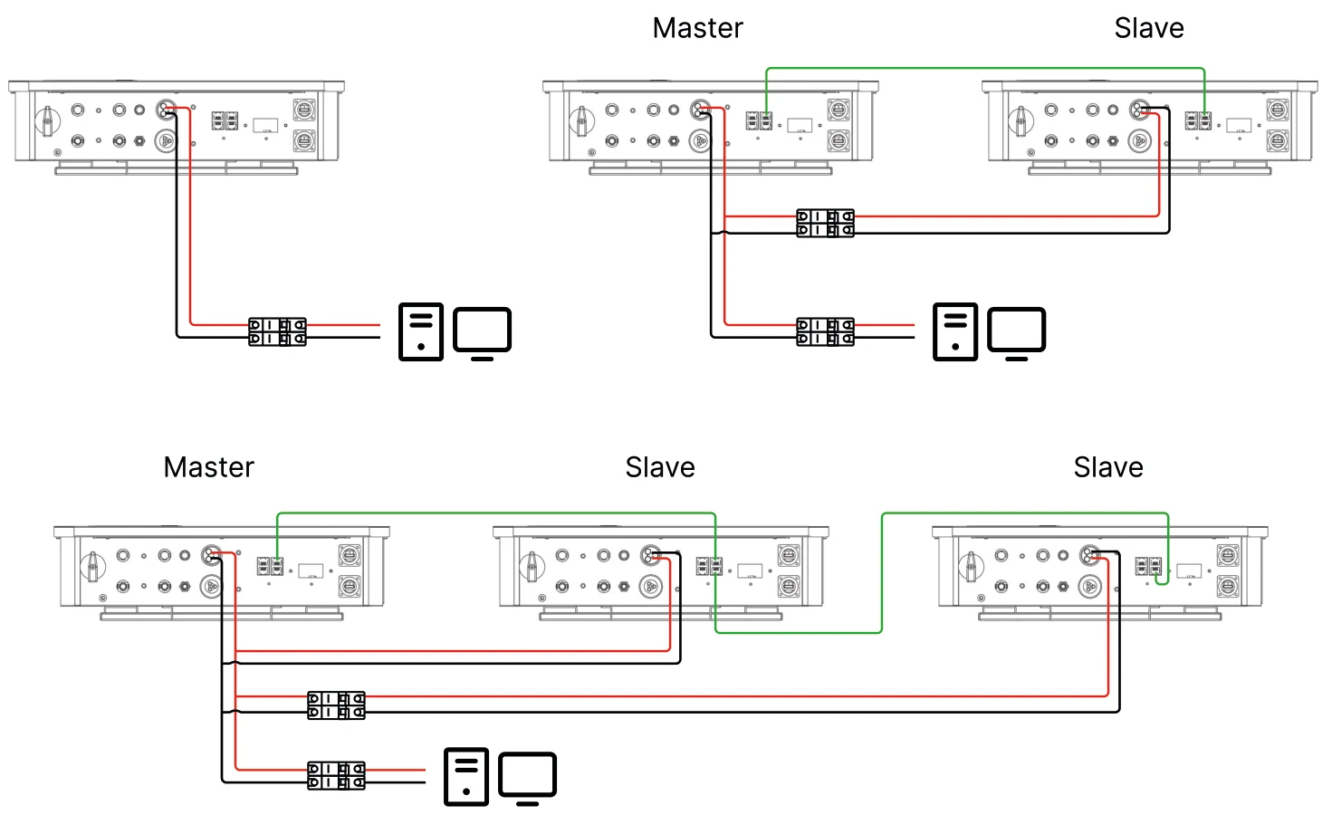
SM8.0kWLLL / SM8.0kWPLL
Grid Connection
SM3.6kWLLL / SM3.6kWPLL
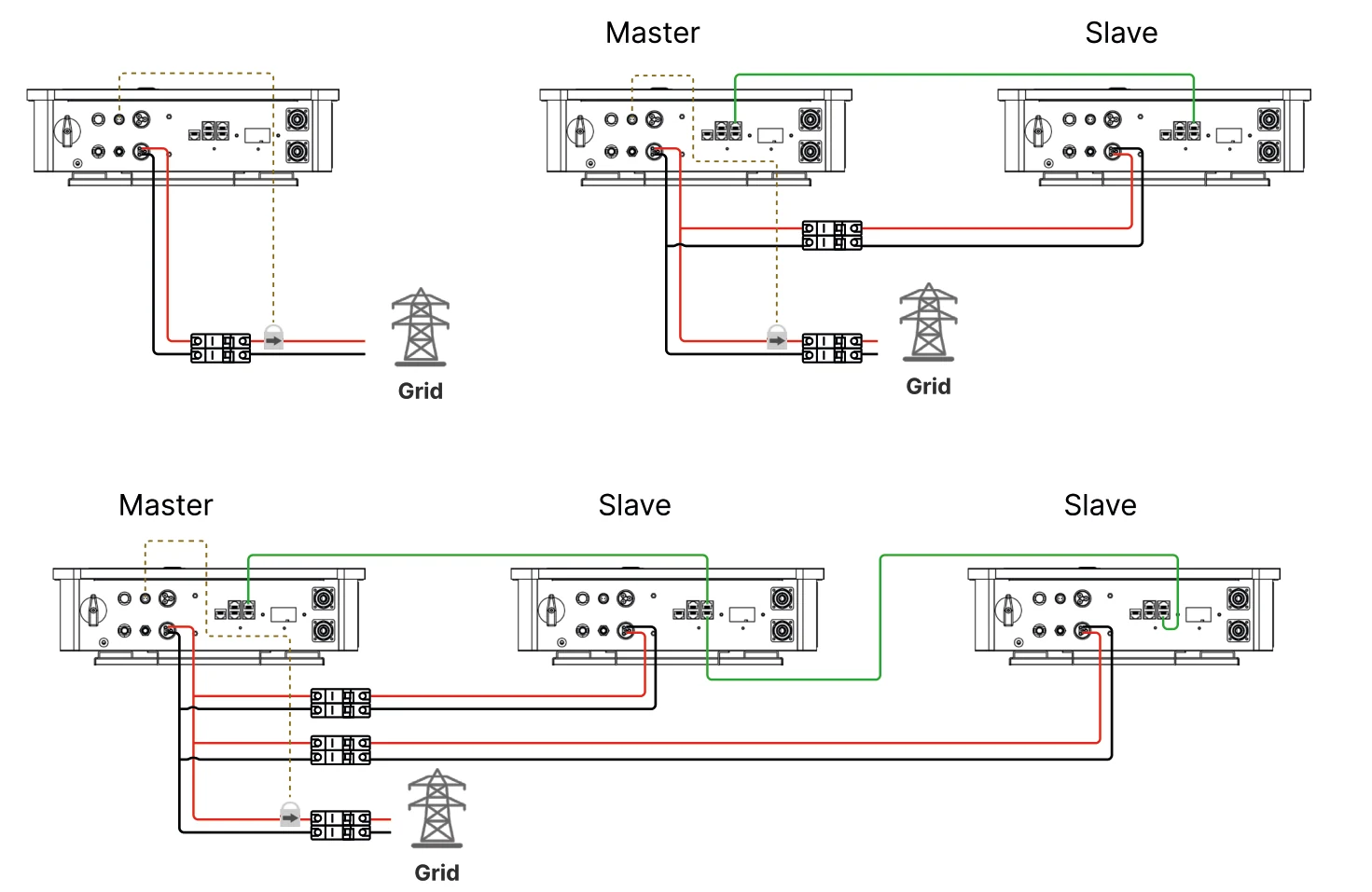
SM6.0kWLLL / SM6.0kWPLL
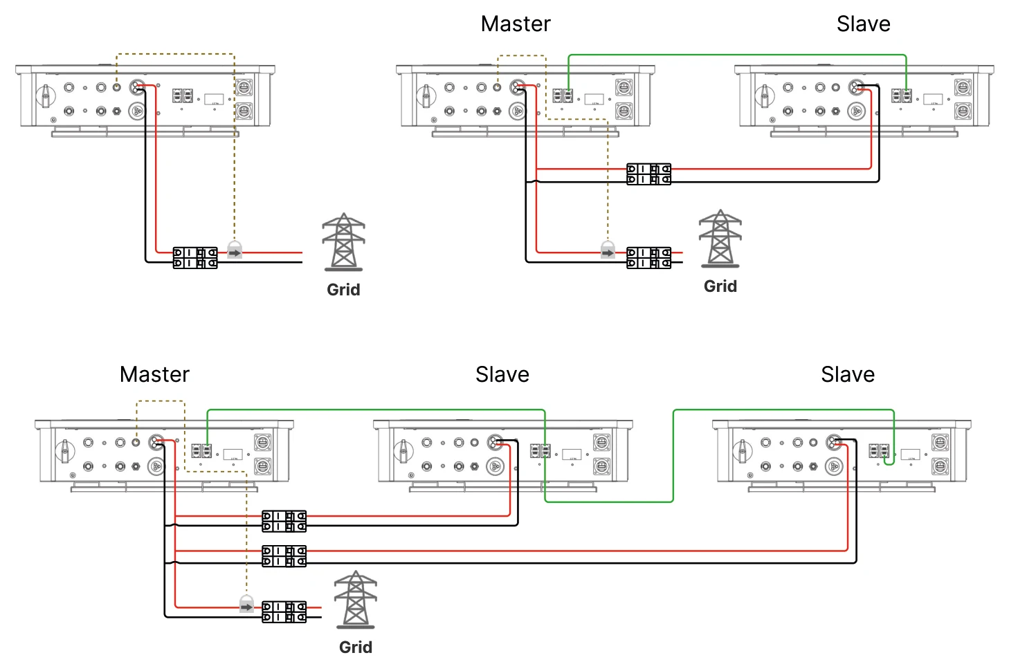
SM8.0kWLLL / SM8.0kWPLL
Solar Connection
SM3.6kWLLL / SM3.6kWPLL
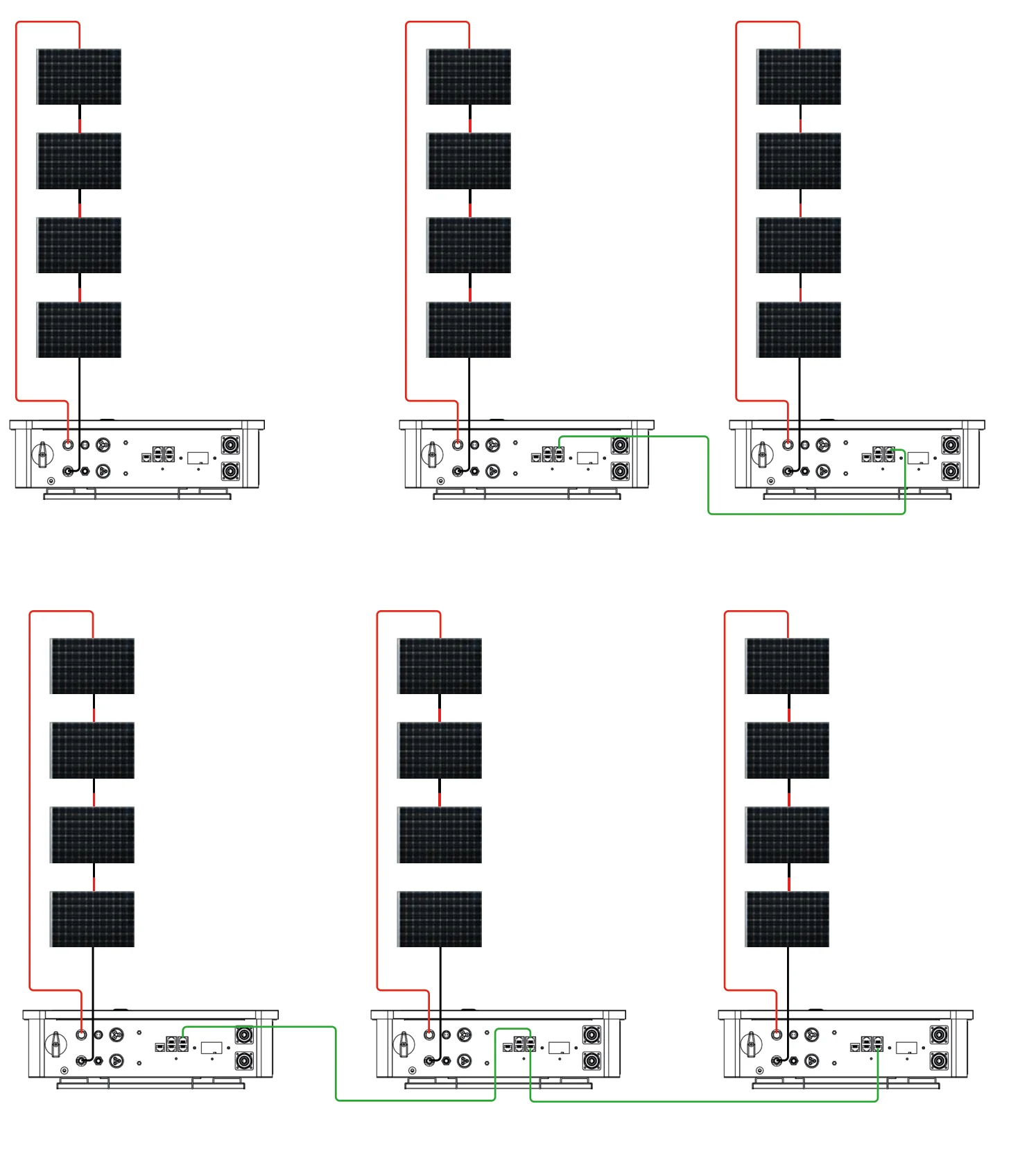
SM6.0kWLLL / SM6.0kWPLL
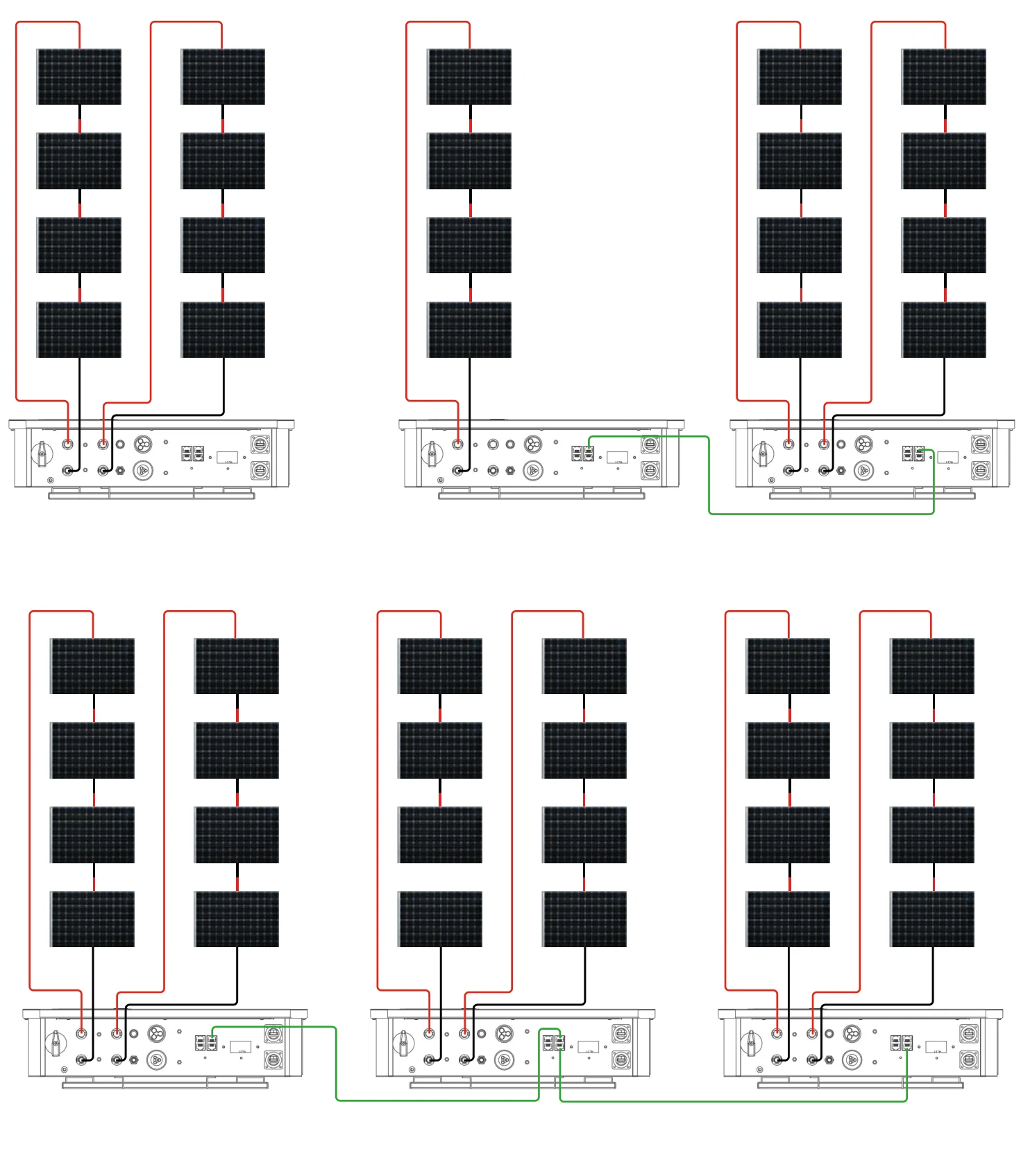
SM8.0kWLLL / SM8.0kWPLL