Electrical Connection
Safety Precautions
- Only qualified electrical professionals may install and operate the product.
- The product may only be used in installations equipped with overvoltage protection devices.
- Do not place the equipment on a flammable surface.
- Do not perform electrical connections during sandstorms, or when the relative humidity of the surrounding environment is greater than 95%.
- Do not contact live parts directly without protection.
- Before installation, ensure there is no voltage on the AC side or the DC side.
- Only connect "+" to "+" and "−" to "−".
- This system must be used with a compatible hybrid inverter. It must establish communication with the inverter to activate lithium battery mode and ensure optimal battery performance.
- When connecting to inverters or operating in parallel mode, use the cables provided in the packing list. If other cables must be used, ensure they comply with the relevant standards.
- Before connecting cables, check that the polarity of all input cables is correct. Do not pull wires and cables forcibly during electrical installation; the insulation performance may be affected. Ensure all cables have sufficient bending space and take auxiliary measures to reduce cable stress.
- After each connection is complete, carefully check that the connection is correct and secure.
Cable Preparation
| Cable Type | Quantity | Modification Needed | Provision Status |
|---|---|---|---|
| Ground wire | 1 | No | In the attached package |
| Positive cable (battery to Power Conversion Unit) | 1 | Yes, for parallel systems | In the attached package |
| Negative cable (battery to Power Conversion Unit) | 1 | Yes, for parallel systems | In the attached package |
| Communication cable (battery to Power Conversion Unit) | 1 | No | In the attached package |
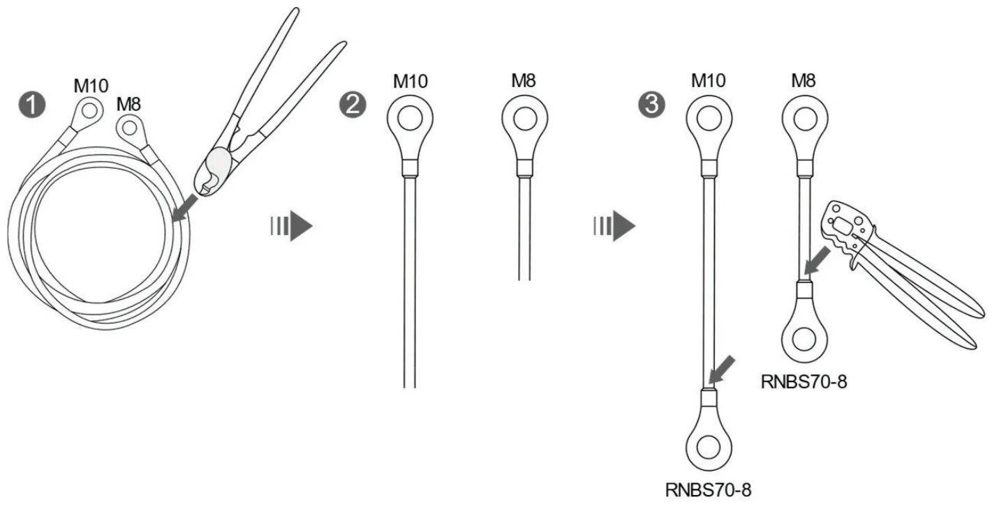
Modifying the Cable for Parallel Systems
- Use the cable cutter to cut the cable harness at the appropriate position.
- After cutting, you will have two cable harnesses, each with a terminal at one end only.
- Take a crimp terminal from the accessory bag and crimp it onto the cut end of each harness with the crimping tool. You will then have two cable harnesses with terminals at both ends.
- The cut position shall be close to the end with the M8 terminal, that is, the end with the smaller terminal hole.
- The exact cut position shall be determined according to the on-site installation conditions.

Battery Preparation
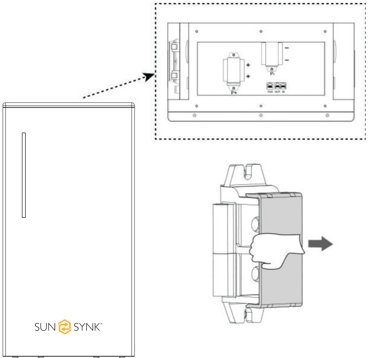
Remove the two plastic covers from the positive and negative terminal blocks in the wiring area on top of the battery pack.
Cable Connection Overview
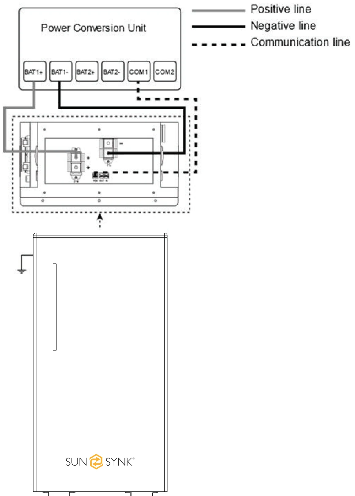
Cable connection without junction box:
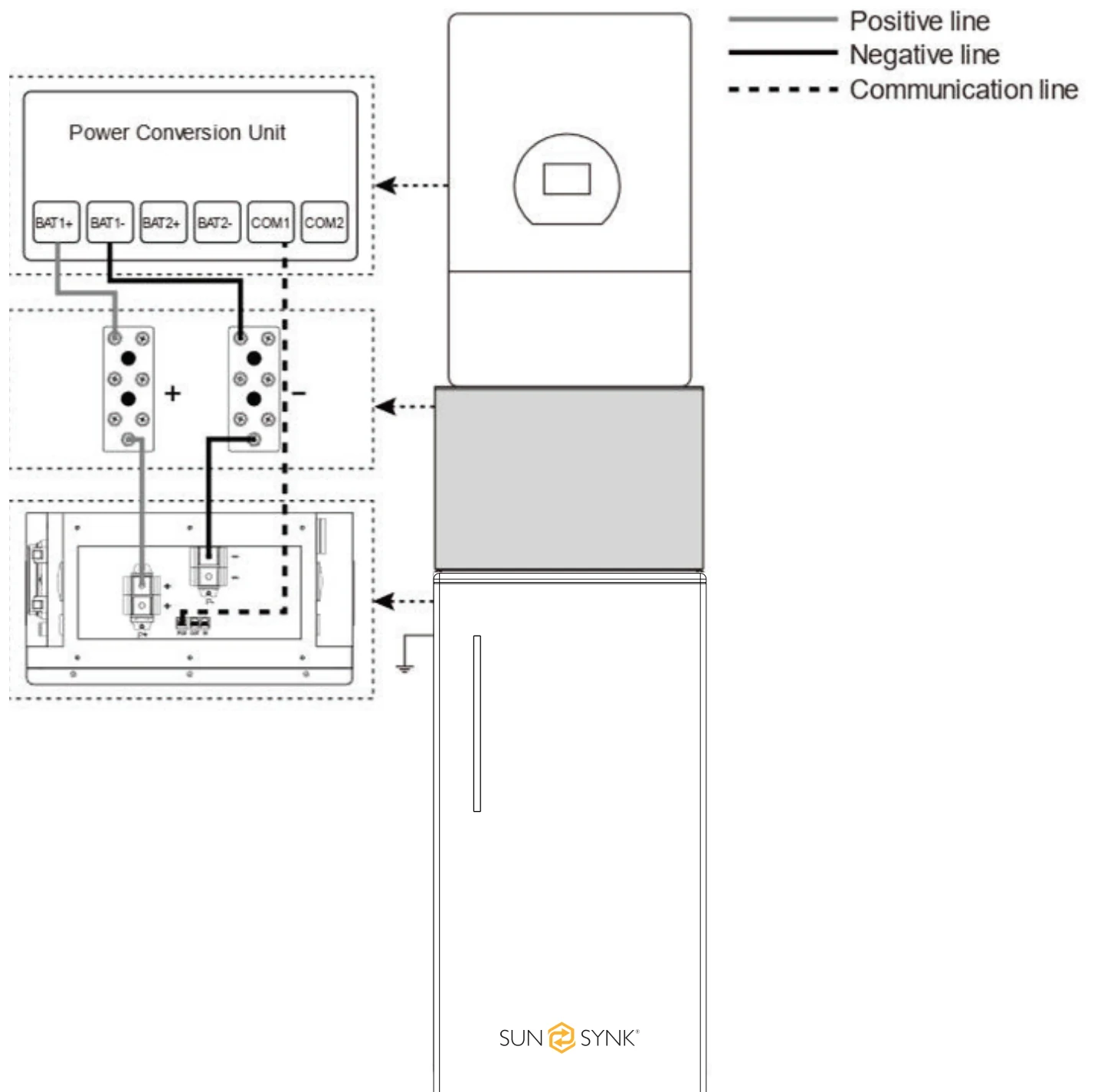
Cable connection with junction box:
Grounding
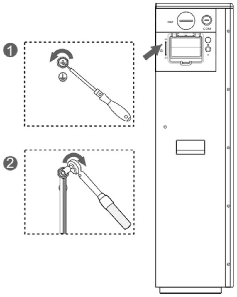
The grounding bolt (M4*8) is pre-installed on the battery at the factory. Follow these steps:
- Unscrew the grounding bolt.
- Connect the grounding wire.
- Re-tighten the bolt to the battery with a recommended torque of 1.2 ~ 1.6 lbf·ft (1.6 ~ 2.2 N·m).
- Connect the other end of the grounding cable reliably to earth ground.
- Confirm a reliable connection at the designated grounding terminal to complete grounding.
Power Cable
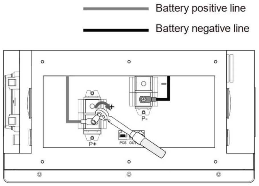
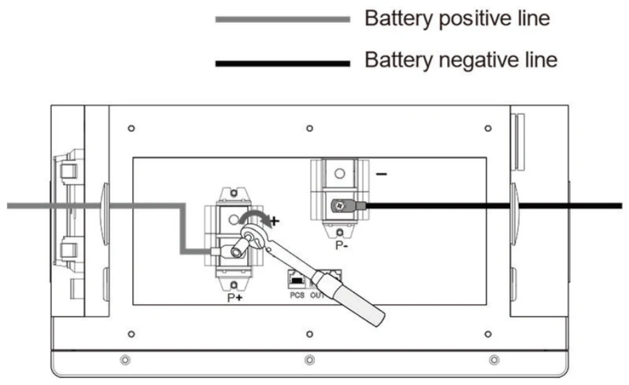
Unscrew the factory-installed M8*20 bolts at the wiring positions, connect the corresponding positive and negative cables, then re-tighten the M8*20 bolts with a recommended torque of 8.9 ~ 14.0 lbf·ft (12 ~ 19 N·m).
Connect the positive and negative cables to the connection busbars in the junction box, or connect them directly to the Power Conversion Unit.
- Do not cross the cables during wiring.
- When wiring power cables via the junction box, do not connect cable terminals to the busbar fixing screws. The busbar fixing screws are marked black in the schematic diagrams.
Power cable routing with junction box:
Power cable routing without junction box:
Communication Cable
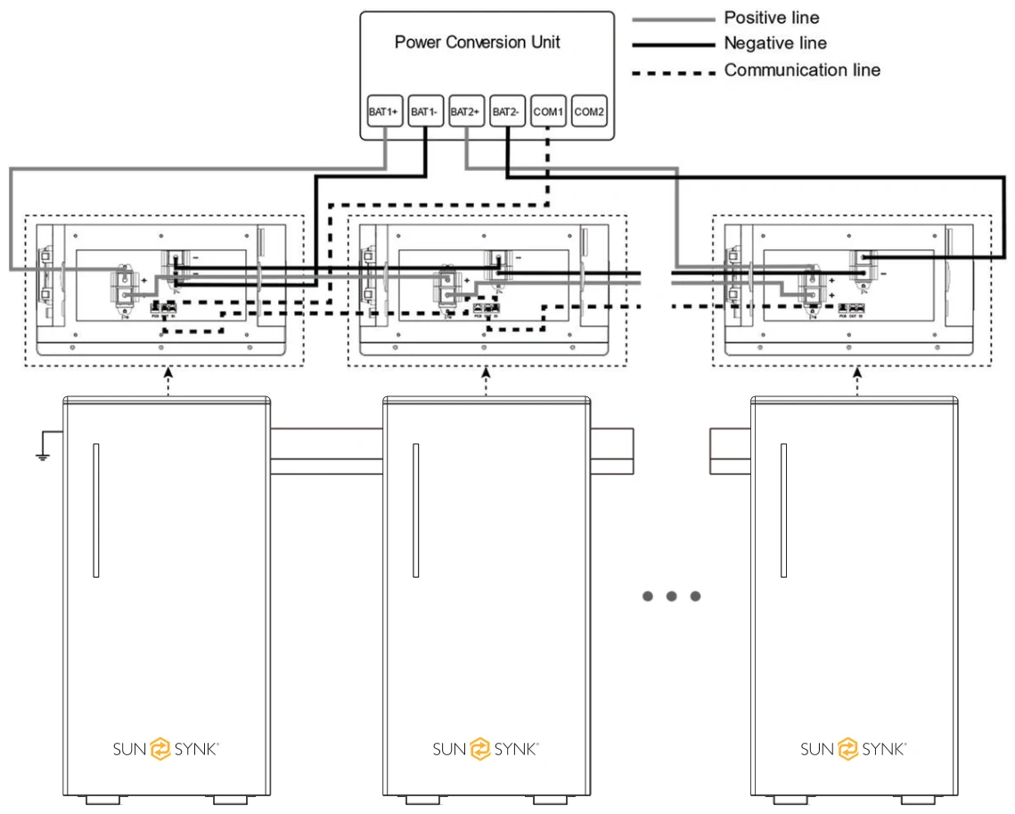
The PCS port is connected to the Power Conversion Unit via the communication cable.
If the battery acts as the master, the OUT port is connected to the IN port of the next battery pack via the communication cable.
If the battery does not act as the master, the IN port is connected to the OUT port of the previous battery pack, and the OUT port is connected to the IN port of the next battery pack — or left unconnected if it is the last unit in the chain.
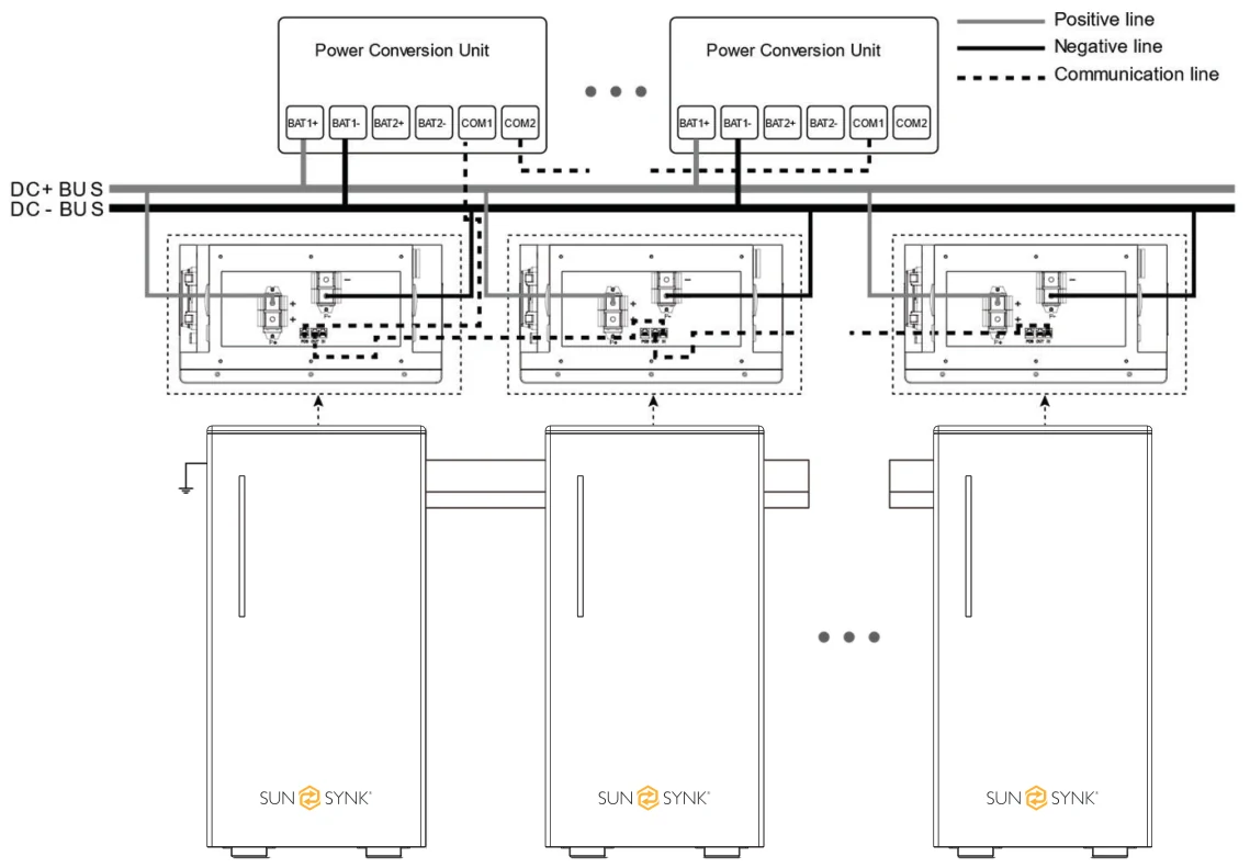
Multi-System without Junction Box
When connecting multiple battery packs, route all cables through steel conduits and connect the conduits to the wiring outlets, whether or not the junction box is used.
Parallel system 1:
Parallel system 2:
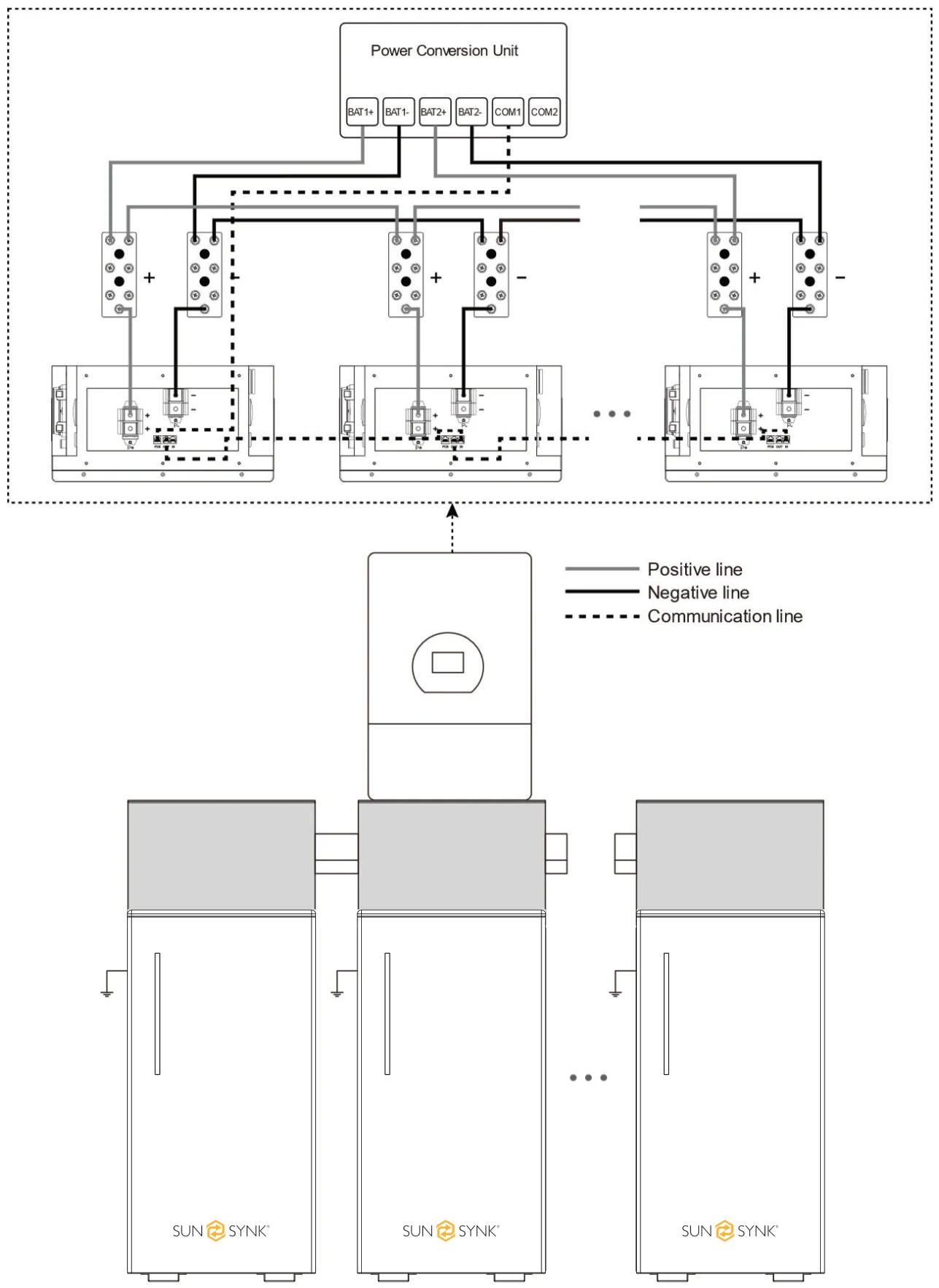
Multi-System with Junction Box
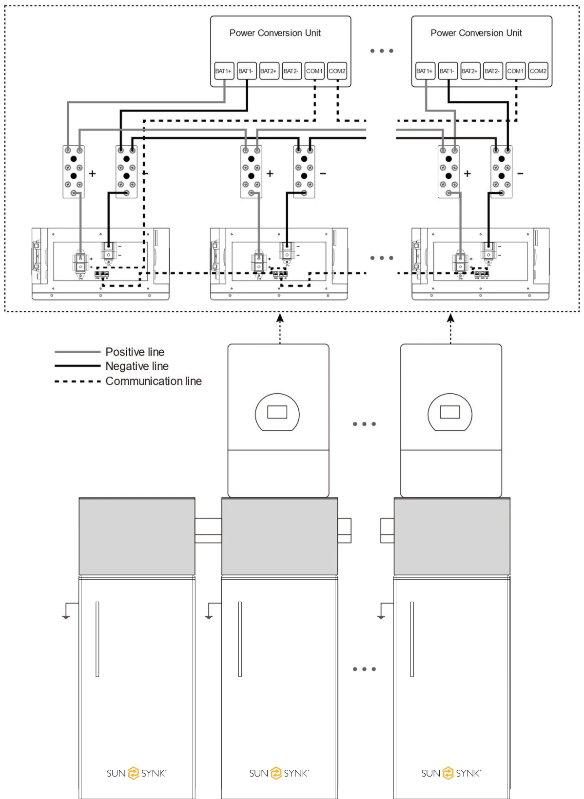
When connecting multiple battery packs, route all cables through steel conduits and connect the conduits to the wiring outlets, whether or not the junction box is used.
Parallel system 1:
Parallel system 2:
Post-Connection Inspection
After connecting the battery, verify the following:
- Correct polarity of the positive and negative cable connections.
- Secure and reliable connection of the positive and negative terminals.
- All bolts tightened to the specified torque values — refer to the Recommended Torque table.
- Proper cable fastening and intact cable appearance.
- Correct and secure installation of the protective cover.