Model Description
The SS-16kWh-F-BATT-IP21-00 is available in three configurations, differentiated by their display and monitoring interface. All three share the same core specifications.
Sunsynk FL 16kWh LV IP21 Whi (SKU Code: 10000421)

Sunsynk FE 16kWh LV IP21 Whi (SKU Code: 10000423)

LED INDICATOR INSTRUCTIONS
Error: Red on the right and green on the left, long bright if equipment protected.
SOC: Battery capacity indicator, green light strip
| Condition | Error | SOC1 0% ~ 20% | SOC 2 0% ~ 40% | SOC 3 0% ~ 60% | SOC 4 0% ~ 80% | SOC 5 0% ~ 100% |
|---|---|---|---|---|---|---|
| SOC | Green light strip | Green light strip | Green light strip | Green light strip | Green light strip | |
| Power off | Off | |||||
| Charge | Off | Show SOC & highest LED blink | ||||
| Discharge or Idle | Off | Show SOC & long bright | ||||
| Alarm | Off | Other LEDs are same as above. | ||||
| System error/ Protect | Red | |||||
| Upgrade | Blink Quickly | |||||
| Critical Error | Blink Slowly | |||||
Sunsynk FC 16kWh LV IP21 Whi (SKU Code: 10000424)

| Condition | Performance |
|---|---|
| Normal | After initialised successfully, the LCD screen will be on for a long time and shows the SOC in percentage. The screen stays on unless in shutdown or dormancy. The indicator in the shape of the Sunsynk logo appears blue. |
| Abnormal | If a fault in the next table occurs, the corresponding fault code will be displayed on the LCD screen. For details, refer to the next table. The indicator in the shape of the Sunsynk logo appears red. |
| Upgrade | When upgrading, the screen will be filled with the "upd" as well as the upgrade process in percentage. The indicator in the shape of Sunsynk appears blue. |
| Others | 1. The Sunsynk indicator displays red and flash quickly when there is a communication failure between the LCD screen and the BMS motherboard. 2. The Sunsynk indicator displays red while the system is upgrading with faults existing. |
Product Overview
The Product Overview provides key information about the SS-16kWh-F-BATT-IP21-00 battery system, helping users understand its components, specifications, and applications.
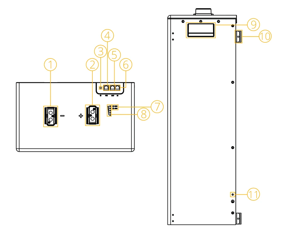
| Ref. | Component | Description |
|---|---|---|
| 1 | P− Port | Negative DC output terminal. |
| 2 | P+ Port | Positive DC output terminal. |
| 3 | Battery Switch | Powers the battery on or off. |
| 4 | PCS Port | Power connection between the battery and the inverter (PCS). |
| 5 | OUT Port (RJ45) | Communication output. Connect to the IN terminal of the next battery, or to the PCS communication terminal. Follows CAN protocol (500 kbps) and RS485 (9600 bps). |
| 6 | IN Port (RJ45) | Communication input. Connect to the OUT terminal of the previous battery in a parallel chain. |
| 7 | Status Indicator (green) | Status LED indicating operational state. See LED Indicator table. |
| 8 | SOC Indicators (×5) | 5 LED lights indicating remaining charge level in 20% increments: 20% / 40% / 60% / 80% / 100%. |
| 9 | Handle | Carrying handle on top of unit. |
| 10 | Bracket Mount | Wall/floor mounting brackets on the rear of the unit. |
| 11 | Protective Earth (PE) | Ground terminal for earthing. |
LED Indicators
The following table describes the RUN and ALM indicator behaviour under each operating condition. SOC indicators (SOC1–SOC5) display remaining charge at all times during operation.
| Condition | RUN | ALM | SOC1 | SOC 2 | SOC 3 | SOC 4 | SOC 5 |
|---|---|---|---|---|---|---|---|
| Power off | Off | ||||||
| Charge | Blink | Blink if Alarm Exists | e.g, SOC67% | ||||
| Off | On | On | On | On | |||
| Discharge or Idle | e.g., SOC47% | ||||||
| Off | Off | Blink | On | On | |||
| Alarm | Blink | Same as 'Discharge of Idle' | |||||
| System error/ Protect | |||||||
| Upgrade | Blink Quickly | ||||||
| Critical Error | Blink Slowly | ||||||
Technical Specifications
Approvals and certification are subject to change without prior notice. Please confirm the current status with Sunsynk before placing an order.
| Model | SS-16kWh-F-BATT-IP21-00 | |
|---|---|---|
| Main Parameters | ||
| Battery Chemistry | LiFePO4 | |
| Nominal Capacity | 314Ah | |
| Scalability [1] | Max. 32 Batteries in Parallel | |
| Nominal Voltage | 51.2V | |
| Operating Voltage | 44.8V~57.6V | |
| Nominal Energy | 16kWh | |
| Charge Current [2] | Recommend | 157A |
| Max. Continuous | 160A | |
| Peak | 280A (10s) | |
| Discharge Current [2] | Recommend | 157A |
| Max. Continuous | 230A | |
| Peak | 280A (10s) | |
| General Specification | ||
| Recommended Depth of Discharge | 90% DoD | |
| Dimension (WxHxD) | 400x708x233mm | |
| Weight (Approx.) | 109kg | |
| Master LED Indicator | LED (SOC, Working, Protecting) & Buzzer | |
| Protection Rating | IP21 | |
| Operating Temperature | Charge: 0 to 55°C Discharge: -20 to 55°C | |
| Storage Temperature | 0°C ~ 35°C | |
| Relative Humidity | 95% (No Condensing) | |
| Altitude | ≤3000m | |
| Cycle Life | ≥6000 (25°C±2°C, 70%EOL) | |
| Installation | Wall-Mounted, Floor-Mounted, Stack-Mounted | |
| Communication Port | CAN2.0, RS485, Bluetooth, App | |
| Energy Throughput [3] | 50MWh | |
| Standard Compliance | ||
| This product complies with ISO and its relevant norms and standards. Approvals and certifications are subject to change without notice. Please verify current status with Sunsynk before ordering. | ||
| Warranty | See website for Warranty details | |
[1] Max. 64 pcs can parallel with CAN-Box.
[2] The current is affected by temperature and SOC. The max. continuous current is only supported in lithium mode; for lead-acid mode, please refer to the manual for the max. continuous current.
[3] Please refer to the Warranty Letter for applicable conditions, the warranty is due whichever comes first.
System Components
System components introduces the main hardware elements, including the battery module, BMS, connectors, and interfaces, to give a clear understanding of the system structure.
Check if you received all the items listed below. Ensure that nothing is damaged in the package.

26AWG 1000mm Communication Cable x1
1000mm Ground Wire x1
Battery Pack x1
Hook x2

1AWG 1000mm Positive Battery Power Cable x1
1AWG 1000mm Negative Battery Power Cable x1
Expansion Bolt x9 (M6*100)
Bolt x4 (M4*10)

User Manual x1pcs
Bracket x4
Bolt x16 (M5*12, Provided with Wheels)
Wheel x4 (Optional)

Logo Sticker x1
Positioning Paperboard x1
Users may apply the logo sticker following the guidance images below. Refer to the images provided for correct sticker placement and distance reference.
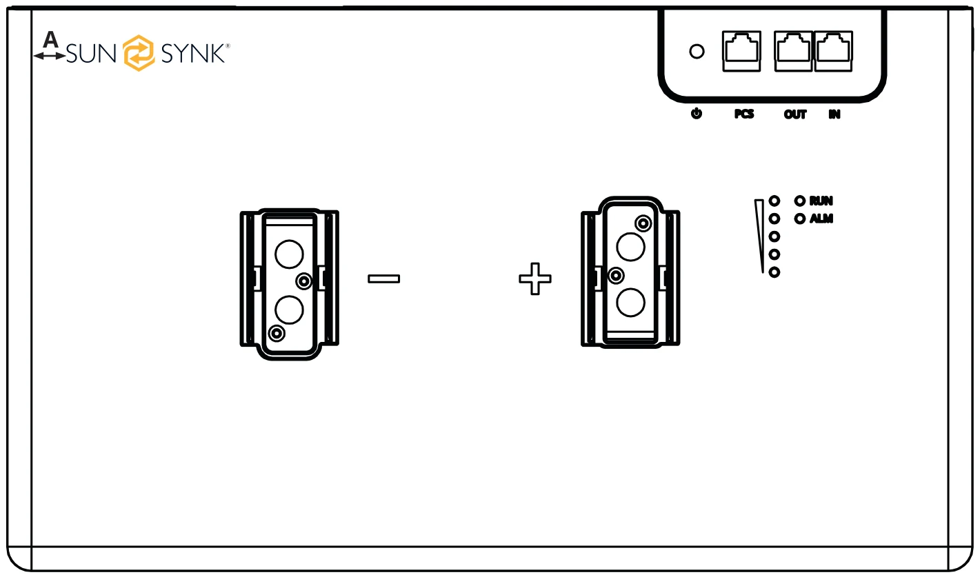
| Item | Minimum Distance (mm) |
|---|---|
| A | 10 |
Required Tools
The following tools are required to install the battery. Use properly insulated tools to prevent accidental electric shock or short circuits. If insulated tools are not available, cover all metal tool surfaces, except the tips, with electrical tape.
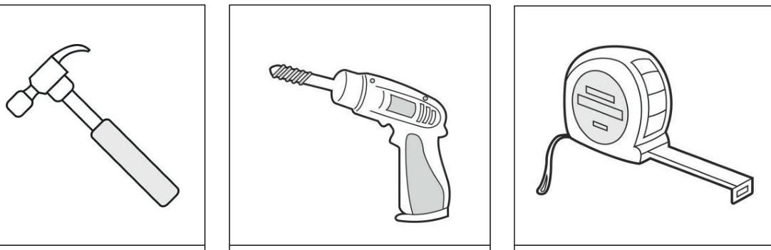
Hammer
Drill
Tape Measure
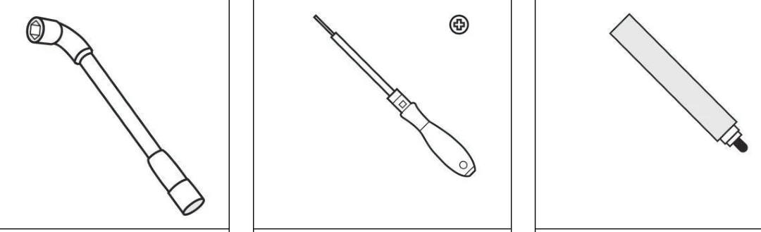
Hexagon Socket Wrench
Phillips Screwdriver
Marker
Safety Gear
It is recommended to wear the following safety gear when handling the battery pack:
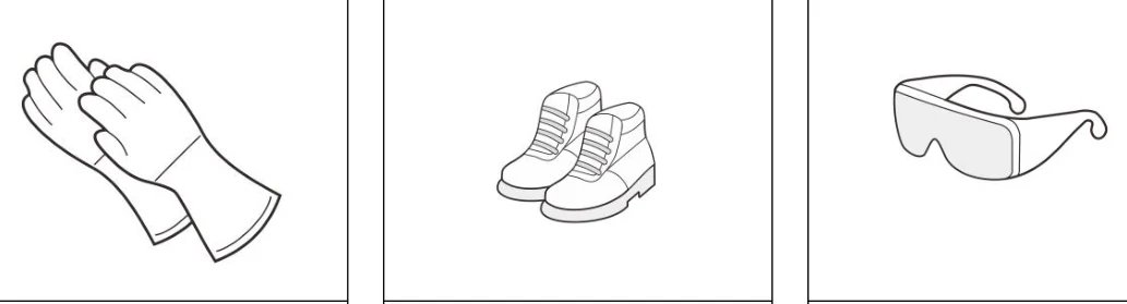
Insulated Gloves
Safety Shoes
Safety Googles